Table 6: MX480 Router Hardware Components and CLI Terminology (continued)
DescriptionCLI NameHardware Model NumberComponent
“MX480 AC Power Supply
Description” on page 100
AC Power Entry ModulePWR-MX480-ACAC power supply
PS 1.2-1.7kW 100-240V AC
in
PWR-MX480-1200-AC
PS 1.4-2.52kW;90-264VAC
in
PWR-MX480-2520-AC
“MX480 DC Power Supply
Description” on page 102
DC Power Entry ModulePWR-MX480-DCDC power supply
DC Power Entry ModulePWR-MX480-1600-DC
DC 2.4kW Power Entry
Module
PWR-MX480-2400-DC
“MX480 Power System
Description” on page 99
N/APWR-BLANK-MX480Power supply blank
panel
Related
Documentation
MX480 Router Description on page 3•
• MX480 DPC Port and Interface Numbering on page 57
• MX480 MIC Port and Interface Numbering on page 77
• MX480 PIC Port and Interface Numbering on page 66
• MX Series Router Interface Names
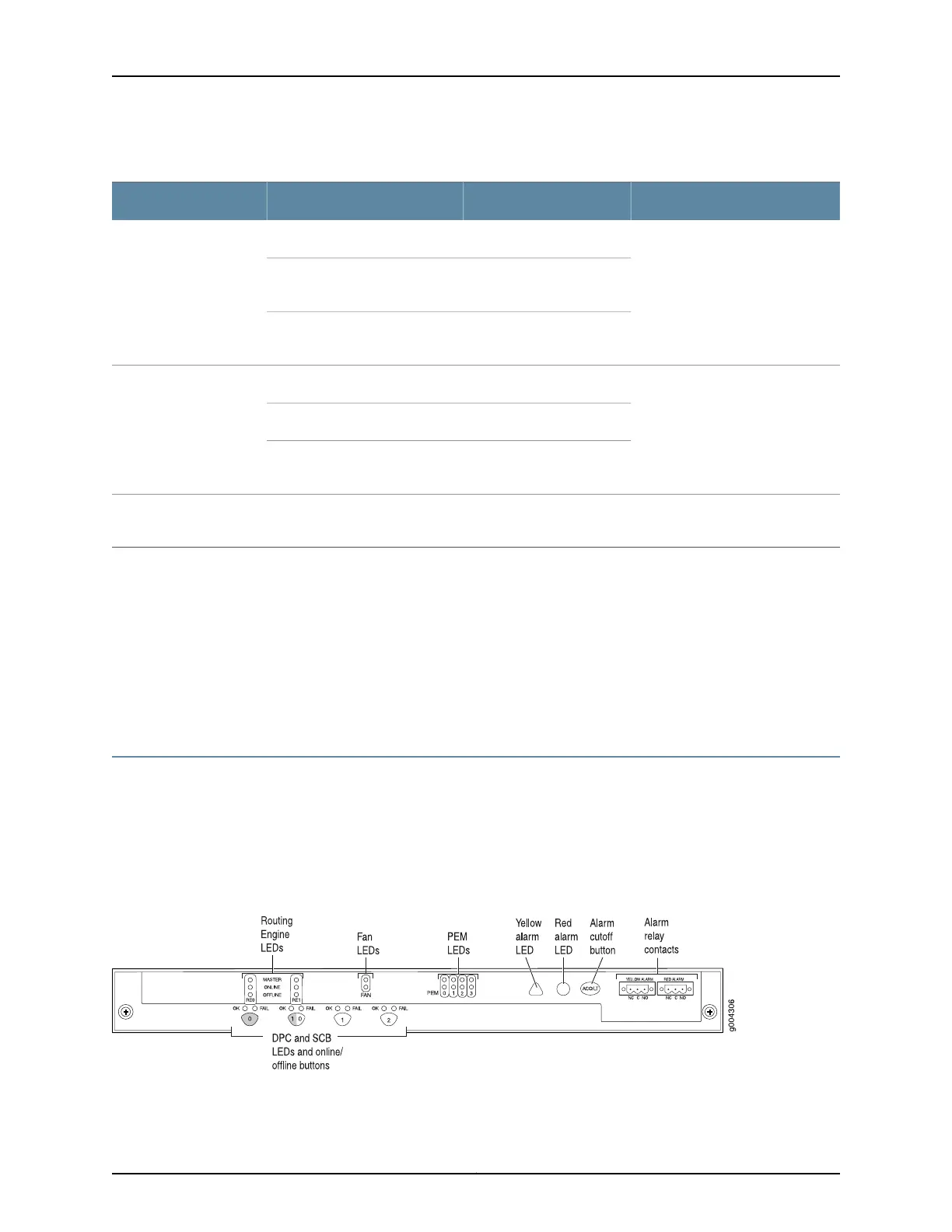
MX480 Craft Interface Description
The craft interface allows you to view status and troubleshooting information at a glance
and to perform many system control functions. It is hot-insertable and hot-removable.
The craft interface is located on the front of the router above the card cage and contains
LEDs for the router components, the alarm relay contacts, and alarm cutoff button. See
Figure 4 on page 14.
Figure 4: Front Panel of the Craft Interface
Copyright © 2017, Juniper Networks, Inc.14
MX480 3D Universal Edge Router Hardware Guide