Connecting the Alarm Relay Wires to the MX480 Craft Interface
To connect the alarm relay wires between a router and an alarm-reporting device (see
Figure 90 on page 239):
1. Prepare the required length of replacement wire with gauge between 28-AWG and
14-AWG (0.08 and 2.08 mm
2
).
2. Insert the replacement wires into the slots in the front of the block. Use a 2.5-mm
flat-blade screwdriver to tighten the screws and secure the wire.
3. Attach an ESD grounding strap to your bare wrist and connect the strap to one of the
ESD points on the chassis.
4. Plug the terminal block into the relay contact, and use a 2.5-mm flat-blade screwdriver
to tighten the screws on the face of the block.
5. Attach the other end of the wires to the external device.
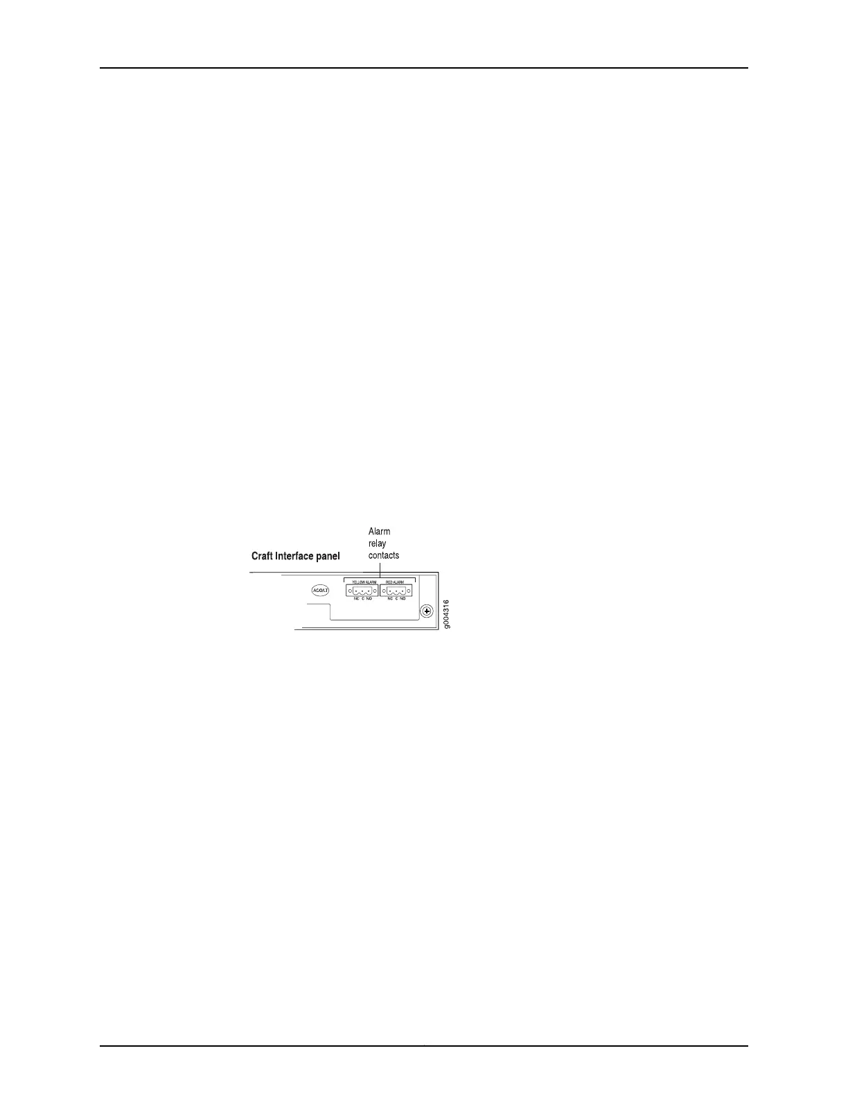
Figure 114: Alarm Relay Contacts
See Also Preventing Electrostatic Discharge Damage to an MX480 Router on page 484•
• Disconnecting the Alarm Relay Wires from the MX480 Craft Interface on page 287
• Removing the MX480 Craft Interface on page 288
• Installing the MX480 Craft Interface on page 251
Related
Documentation
Preventing Electrostatic Discharge Damage to an MX480 Router on page 484•
• MX480 Craft Interface Description on page 14
• Alarm LEDs and Alarm Cutoff/Lamp Test Button on the MX480 Craft Interface on
page 15
Copyright © 2017, Juniper Networks, Inc.290
MX480 3D Universal Edge Router Hardware Guide