3. Plug the female DB-9 end into the device's serial port.
NOTE:
For console devices, configure the serial port to the following values:
•
Baud rate—9600
•
Parity—N
•
Data bits—8
•
Stop bits—1
•
Flow control—none
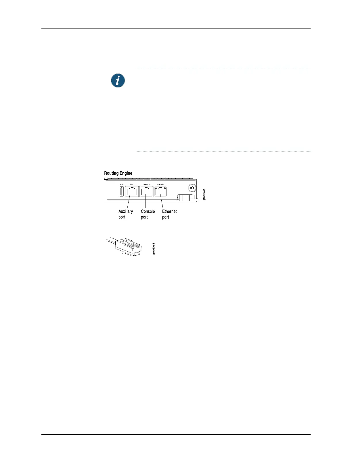
Figure 80: Auxiliary and Console Ports
Figure 81: Routing Engine Console and Auxiliary Cable Connector
See Also Routing Engine Interface Cable and Wire Specifications for MX Series Routers on
page 134
•
• Tools and Parts Required for MX480 Router Connections on page 231
Connecting the MX480 Router to an External Alarm-Reporting Device
To connect the router to external alarm-reporting devices, attach wires to the RED and
YELLOW relay contacts on the craft interface. (See Figure 82 on page 234.) A system
condition that triggers the red or yellow alarm LED on the craft interface also activates
the corresponding alarm relay contact.
The terminal blocks that plug into the alarm relay contacts are supplied with the router.
They accept wire of any gauge between 28-AWG and 14-AWG (0.08 and 2.08 mm
2
),
which is not provided. Use the gauge of wire appropriate for the external device you are
connecting.
233Copyright © 2017, Juniper Networks, Inc.
Chapter 18: Connecting the MX480 Router to the Network