connect it to the AUX port on the Routing Engine. Both ports accept a cable with an RJ-45
connector. One RJ-45/DB-9 cable is provided with the router. If you want to connect a
device to both ports, you must supply another cable.
To replace a cable connected to a management console or auxiliary device:
1. Attach an ESD grounding strap to your bare wrist and connect the strap to one of the
ESD points on the chassis.
2. Press the tab on the connector, and pull the connector straight out of the port.
3. Disconnect the cable from the console or auxiliary device.
4. Plug the RJ-45 end of the replacement serial cable into the CONSOLE or AUX port.
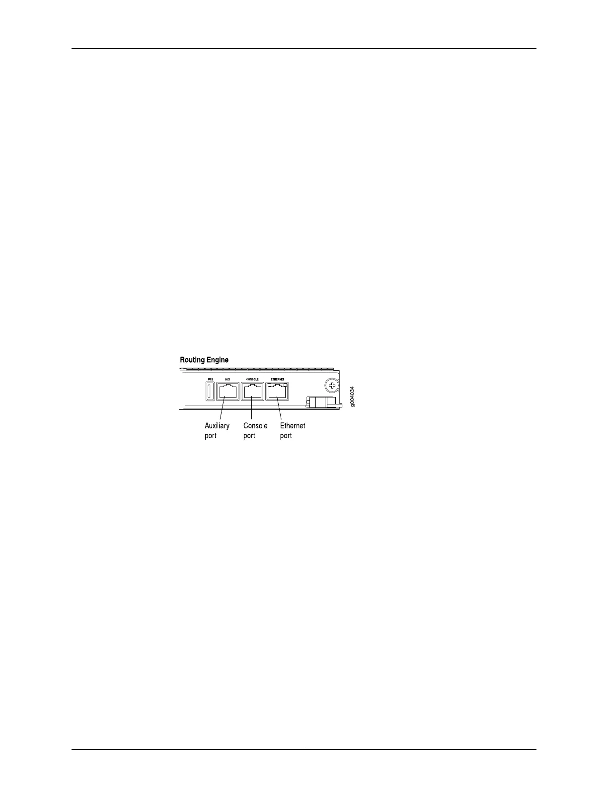
Figure 118 on page 293 shows the external device ports on the Routing Engine.
5. Plug the female DB-9 end into the console or auxiliary device's serial port.
Figure 118: Auxiliary and Console Ports
Related
Documentation
• Routing Engine Interface Cable and Wire Specifications for MX Series Routers on
page 134
• Replacing the Management Ethernet Cable on an MX Series Router on page 292
• Preventing Electrostatic Discharge Damage to an MX480 Router on page 484
293Copyright © 2017, Juniper Networks, Inc.
Chapter 22: Replacing Chassis Components