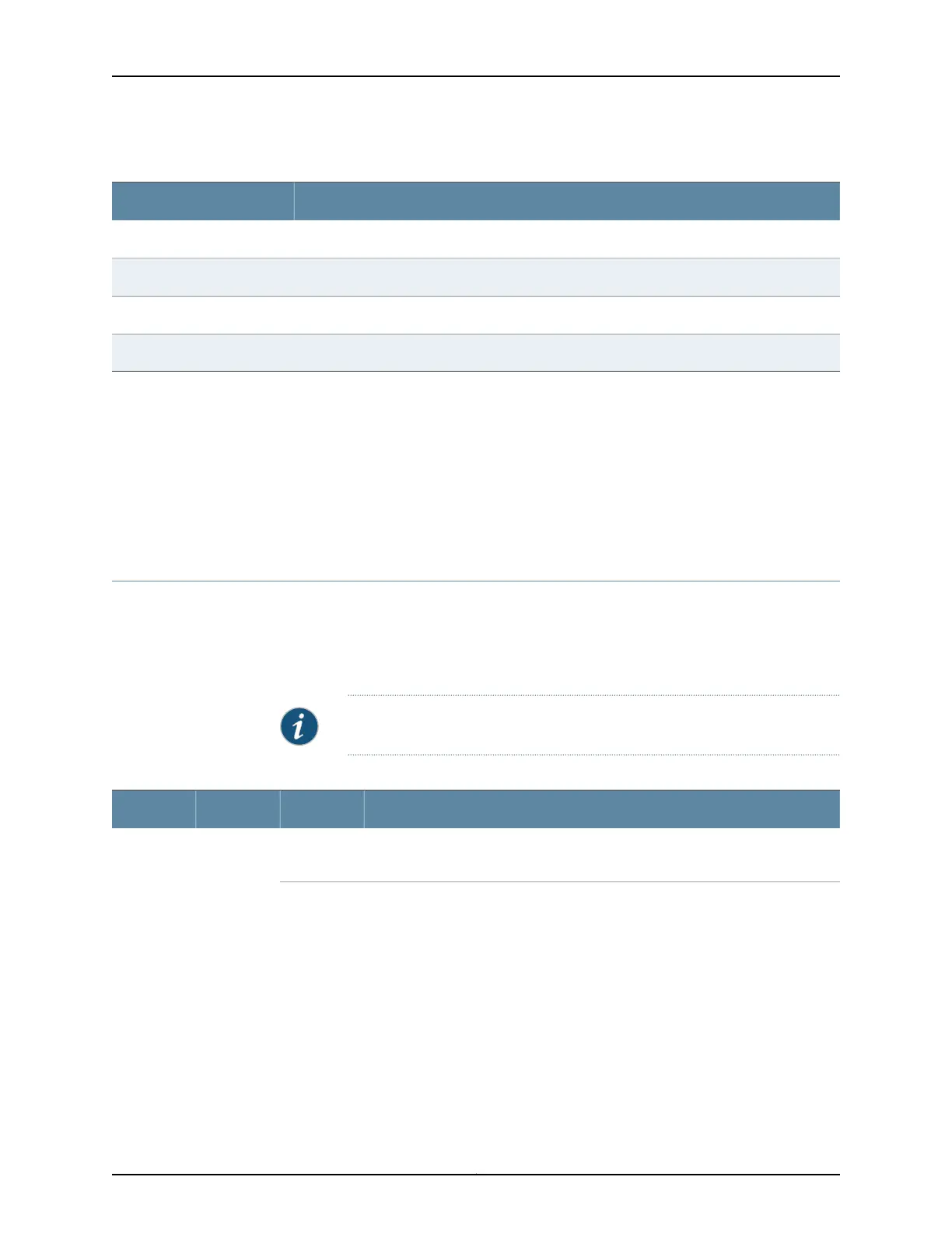
Table 63: Power Supply Redundancy and Power Distribution
Power Supply Provides Power to the Following ComponentsDC Power Supply Slot
Fan tray, DPC slots 0 and 1, and SCB slots 0 and 1PEM0
Fan tray and DPC slots 2 through 5PEM1
Fan tray, DPC slots 0 and 1, and SCB slots 0 and 1PEM2
Fan tray and DPC slots 2 through 5PEM3
Related
Documentation
Power Supply LEDs on the MX480 Craft Interface on page 17•
• MX480 Power System Description on page 99
• MX480 AC Power Supply Description on page 100
• MX480 DC Power Supply LEDs on page 104
• DC Power Supply Electrical Specifications for the MX480 Router on page 157
MX480 DC Power Supply LEDs
Each DC power supply faceplate contains three LEDs that indicate the status of the
power supply (see Table 64 on page 104). The power supply status is also reflected in
two LEDs on the craft interface.In addition, a power supply failure triggers the red alarm
LED on the craft interface.
NOTE: An SCB must be present for the PWR OK LED to go on.
Table 64: DC Power Supply LEDs
DescriptionStateColorLabel
Power supply is not functioning normally. Check the INPUT OK LED for more
information.
OffGreenPWR OK
Copyright © 2017, Juniper Networks, Inc.104
MX480 3D Universal Edge Router Hardware Guide