CHAPTER 4
Cooling System Components and
Descriptions
•
MX480 Cooling System Description on page 21
•
MX480 Fan LED on page 23
MX480 Cooling System Description
The cooling system consists of the following components:
•
Fan tray
•
Air filter
The cooling system components work together to keep all router components within the
acceptable temperature range (see Figure 8 on page 21, Figure 9 on page 22, and
Figure 10 on page 22). The router has one fan tray and one air filter that install vertically
in the rear of the router. The fan tray contains six fans. The MX Series high-capacity fan
trays satisfy cooling requirements for high-density DPCs and MPCs, and must be upgraded
for proper cooling.
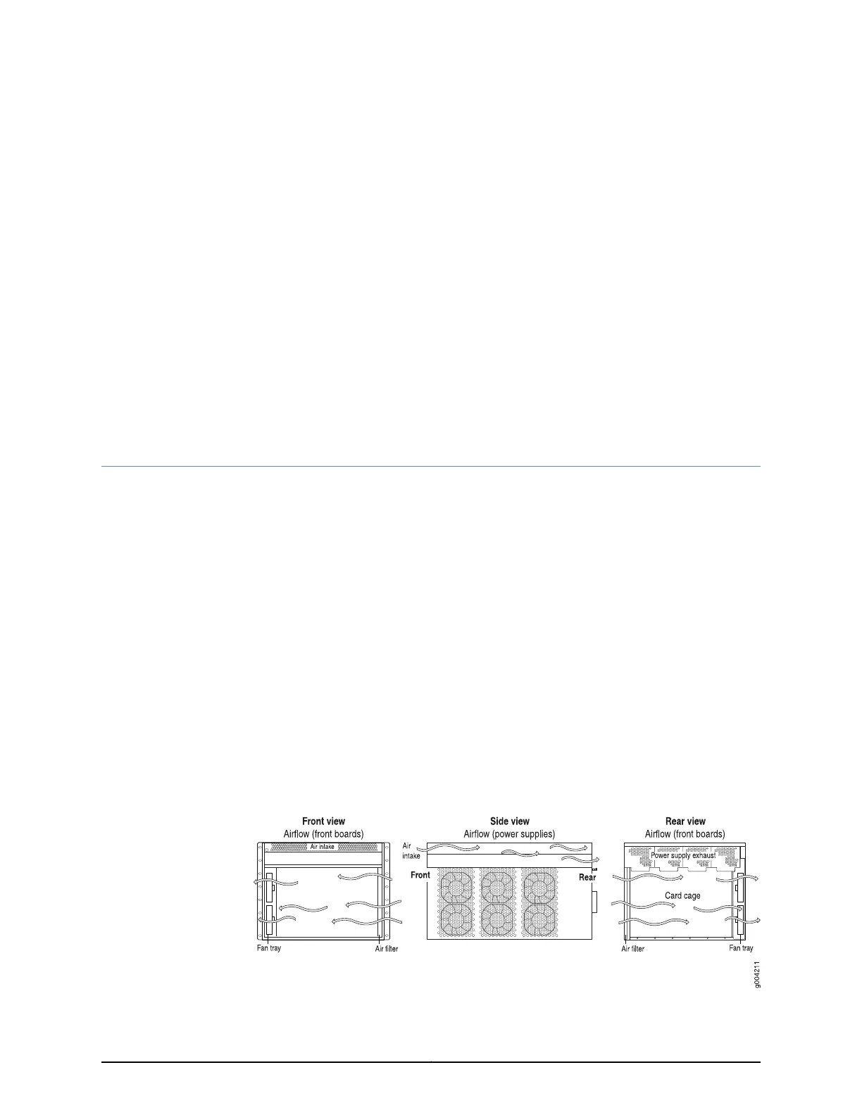
The air intake to cool the chassis is located on the side of the chassis next to the air filter.
Air is pulled through the chassis toward the fan tray, where it is exhausted out the side
of the system. The air intake to cool the power supplies is located in the front of the router
above the craft interface. The exhaust for the power supplies is located on the rear
bulkhead power supplies.
Figure 8: Airflow Through the Chassis
21Copyright © 2017, Juniper Networks, Inc.