DC Power Source Cabling for the MX480 Router
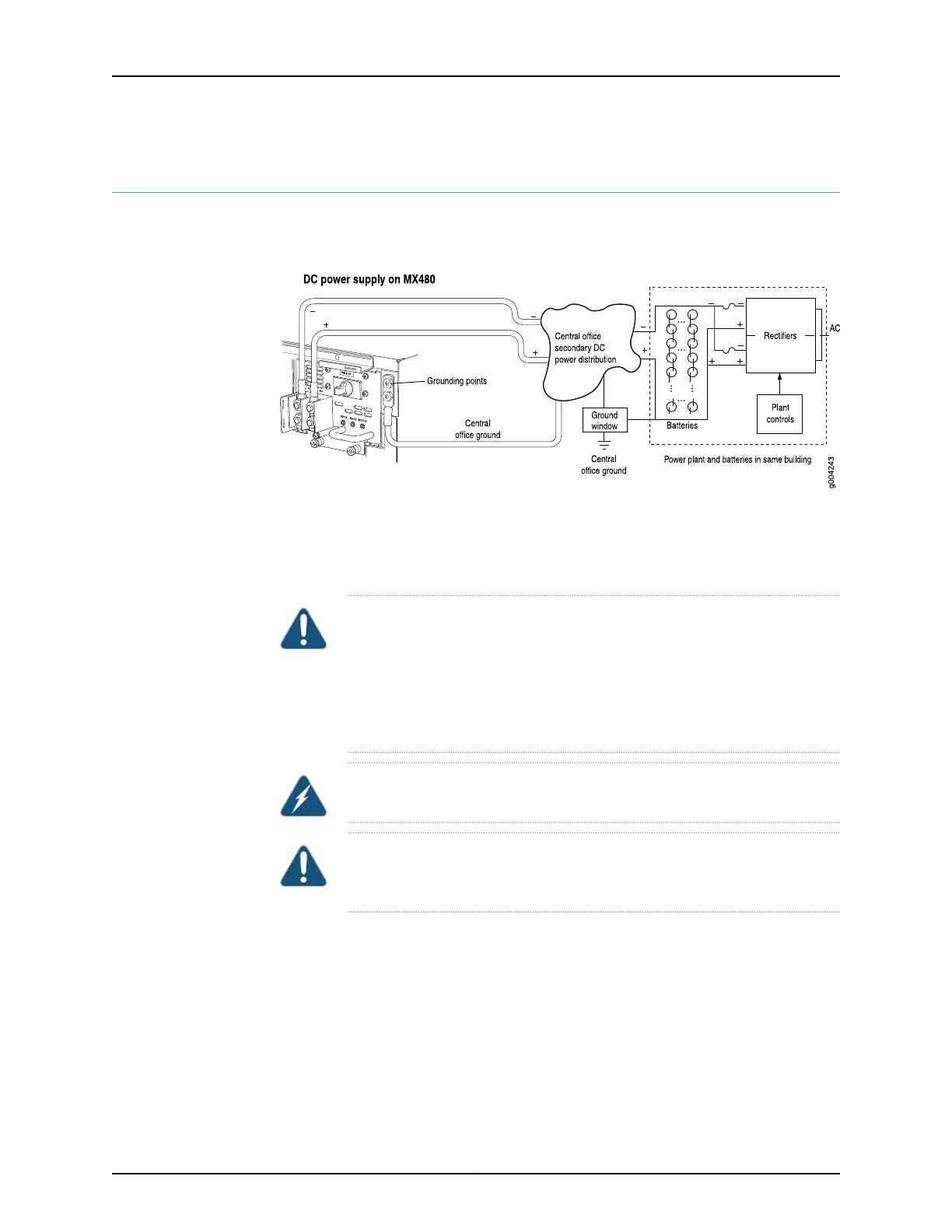
Figure 47 on page 172 shows a typical DC source cabling arrangement.
Figure 47: Typical DC Source Cabling to the Router
The DC power supplies in PEM0 and PEM1 must be powered by dedicated power feeds
derived from feed A, and the DC power supplies in PEM2 and PEM3 must be powered by
dedicated power feeds derived from feed B. This configuration provides the commonly
deployed A/B feed redundancy for the system.
CAUTION: You must ensure that power connections maintain the proper
polarity. The power source cables might be labeled (+) and (–) to indicate
their polarity. There is no standard color coding for DC power cables. The
color coding used by the external DC power source at your site determines
the color coding for the leads on the power cables that attach to the terminal
studs on each power supply.
WARNING: For field-wiring connections, use copper conductors only.
CAUTION: Power cords and cables must not block access to device
components or drape where people could trip on them.
Related
Documentation
In Case of an Electrical Accident•
• MX480 DC Power Supply Description on page 102
• Connecting Power to a DC-Powered MX480 Router with Normal Capacity Power
Supplies on page 221
• Replacing an MX480 DC Power Supply Cable on page 377
Copyright © 2017, Juniper Networks, Inc.172
MX480 3D Universal Edge Router Hardware Guide