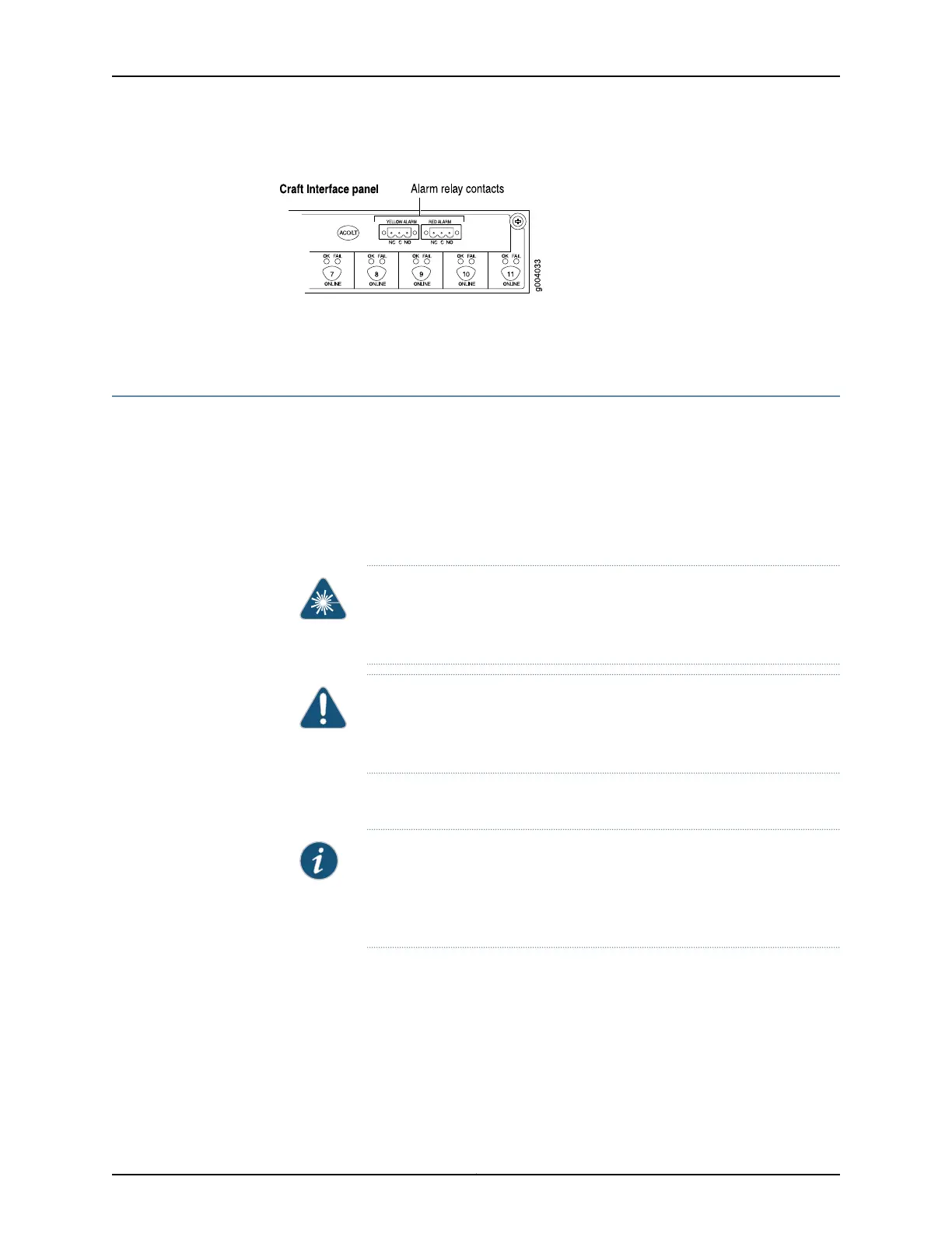
Figure 87: Alarm Relay Contacts
Related
Documentation
Tools and Parts Required for MX480 Router Connections on page 231•
Connecting DPC, MPC, MIC, or PIC Cables to the MX480 Router
To connect the DPCs, MPCs, MICs, or PICs to the network (see Figure 88 on page 238 and
Figure 89 on page 238):
1. Have ready a length of the type of cable used by the component. For cable
specifications, see the MX Series Interface Module Reference.
2. Remove the rubber safety plug from the cable connector port.
WARNING: Do not look directly into a fiber-optic transceiver or into the
ends of fiber-optic cables. Fiber-optic transceivers and fiber-optic cable
connected to a transceiver emit laser light that can damage your eyes.
CAUTION: Do not leave a fiber-optic transceiver uncovered except when
inserting or removing cable. The safety cap keeps the port clean and
prevents accidental exposure to laser light.
3. Insert the cable connector into the cable connector port on the faceplate.
NOTE: The XFP cages and optics on the componentsareindustry standard
parts that have limited tactile feedback for insertion of optics and fiber.
You need to insert the optics and fiber firmly until the latch is securely in
place.
4. Arrange the cable to prevent it from dislodging or developing stress points. Secure
the cable so that it is not supporting its own weight as it hangs to the floor. Place
excess cable out of the way in a neatly coiled loop.
237Copyright © 2017, Juniper Networks, Inc.
Chapter 18: Connecting the MX480 Router to the Network