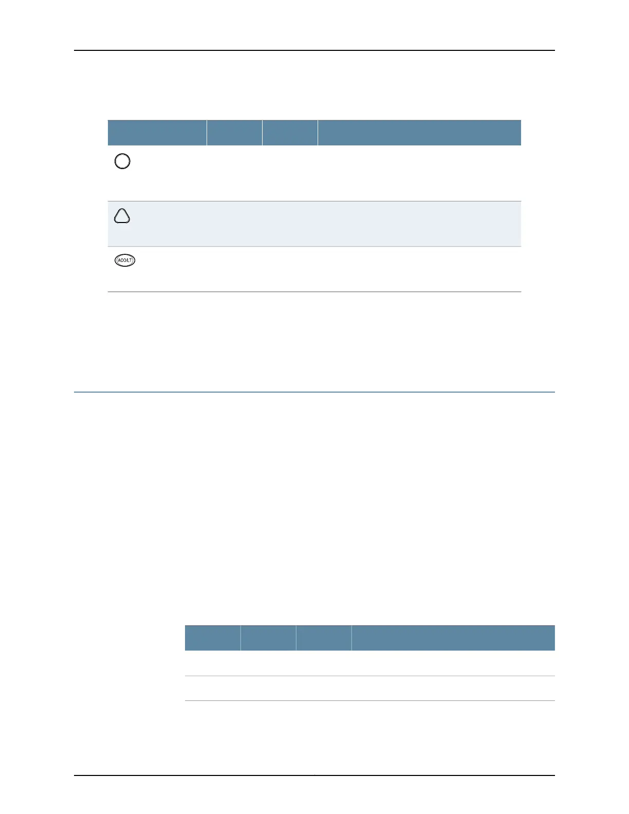
Table 7: Alarm LEDs and Alarm Cutoff/Lamp Test Button
DescriptionStateColorShape
Critical alarm LED—Indicates a critical condition that
can cause the router to stop functioning. Possible
causes include component removal, failure, or
overheating.
On steadilyRed
Warning alarm LED—Indicates a serious but nonfatal
error condition, such as a maintenance alert or a
significant increase in component temperature.
On steadilyYellow
Alarm cutoff/lamptestbutton—Deactivatesredand
yellow alarms. Causes all LEDs on the craft interface
to light (for testing) when pressed and held.
––
Related
Documentation
MX480 Craft Interface Description on page 14•
• MX480 Component LEDs on the Craft Interface on page 16
• Alarm Relay Contacts on the MX480 Craft Interface on page 15
MX480 Component LEDs on the Craft Interface
•
Host Subsystem LEDs on the MX480 Craft Interface on page 16
•
Power Supply LEDs on the MX480 Craft Interface on page 17
•
DPC and MPC LEDs on the MX480 Craft Interface on page 17
•
FPC LEDs on the MX480 Craft Interface on page 17
•
SCB LEDs on the MX480 Craft Interface on page 18
•
Fan LEDs on the MX480 Craft Interface on page 18
Host Subsystem LEDs on the MX480 Craft Interface
Each host subsystem has three LEDs, located on the upper left of the craft interface, that
indicate its status. The LEDs labeled RE0 show the status of the Routing Engine in slot
0 and the SCB in slot 0. The LEDs labeled RE1 show the status of the Routing Engine and
SCB in slot 1. Table 5 on page 7 describes the functions of the host subsystem LEDs on
the craft interface.
Table 8: Host Subsystem LEDs on the Craft Interface
DescriptionStateColorLabel
Host is functioning as the master.On steadilyGreenMASTER
Host is online and is functioning normally.On steadilyGreenONLINE
Copyright © 2017, Juniper Networks, Inc.16
MX480 3D Universal Edge Router Hardware Guide