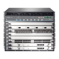
SCBE2 Slots
You can install either one or two SCBE2s. SCBE2s are installed horizontally into the front
of the chassis in the slots labeled 0 and 1. If any slots are empty, you must install a blank
panel.
SCBE2 Redundancy
The control boards operate in redundancy fabric mode by default. You can configure the
control board to be in redundancy mode or in increased fabric bandwidth mode.
For the MX480 router in redundant fabric mode, four of the fabric planes from the first
SCBE2 will be in Active mode, and four from the second SCBE2 will be in Spare mode.
Whereas, in an increased fabric bandwidth mode, all the eight fabric planes will be in
Active mode.
SCBE2 Components
Each SCBE2 consists of the following components:
•
I2C bus logic, used for low-level communication with each component
•
Component-redundancy circuitry
•
Control Board/Routing Engine mastership mechanism
•
Gigabit Ethernet switch that is connected to the embedded CPU complex on all
components
•
External clock interface—Allows BITS or GPS clock source input to the centralized
timing circuit, or allows centralized timing to be output to BITS or GPS
•
Switch fabric—Provides switching functions for the MPCs
•
Control field-programmable gate array (FPGA)—Provides the Peripheral Component
Interconnect (PCI) interface to the Routing Engine
•
1000Base-T Ethernet controller—Provides a 1-Gbps Ethernet link between the Routing
Engines
•
Circuits for chassis management and control
•
Power circuits for the Routing Engine and SCBE2
•
LEDs—Provide status of the SCBE2 and clocking interface
Related
Documentation
•
MX480 SCBE2 LEDs
FABRIC ACTIVE, FABRIC ONLY, and OK/FAIL LEDs indicate the status of the SCBE2. The
BITS, GPS, and UTI LEDs, located next to the EXT CLK port, indicate the status of the
respective clocking interface. The LINK LED located next to the two Ethernet ports,
Copyright © 2017, Juniper Networks, Inc.114
MX480 3D Universal Edge Router Hardware Guide

 Loading...