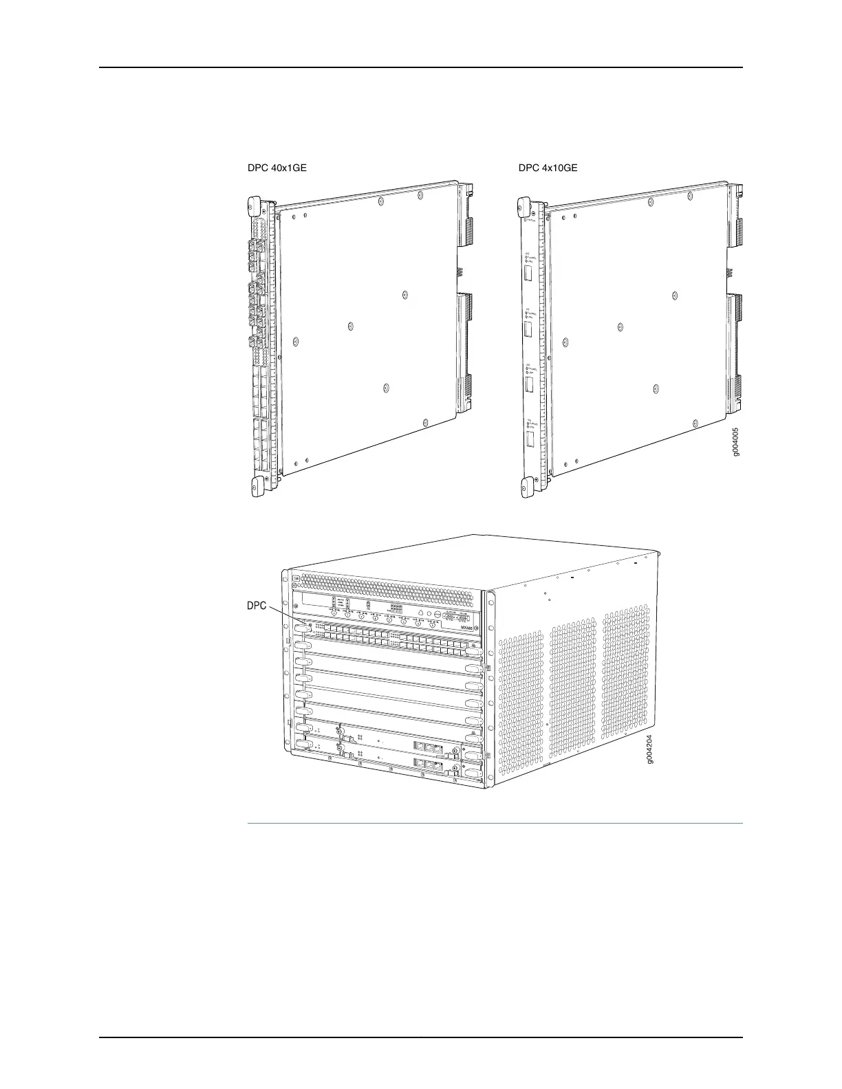
Figure 21: Typical DPCs Supported on the Router
OK/FAIL
TUNNEL
LINK
1/0
TUNNEL
LINK
0/0
TUNNEL
LINK
2/0
TUNNEL
LINK
3/0
OK/
F
AIL
0/0
0/5
2/0
2/5
1/0
1/5
3/0
3/5
g004005
DPC 40x1GE DPC 4x10GE
Figure 22: DPC Installed Horizontally in the Router
DPC Components
Each DPC consists of the following components:
•
DPC cover, which functions as a ground plane and a stiffener.
•
Fabric interfaces.
•
Two Gigabit Ethernet interfaces that allow control information, route information, and
statistics to be sent between the Routing Engine and the CPU on the DPCs.
•
Two interfaces from the SCBs that enable the DPCs to be powered on and controlled.
Copyright © 2017, Juniper Networks, Inc.56
MX480 3D Universal Edge Router Hardware Guide