MX480 Router Clearance Requirements for Airflow and Hardware Maintenance
When planning the installation site, you need to allow sufficient clearance around the
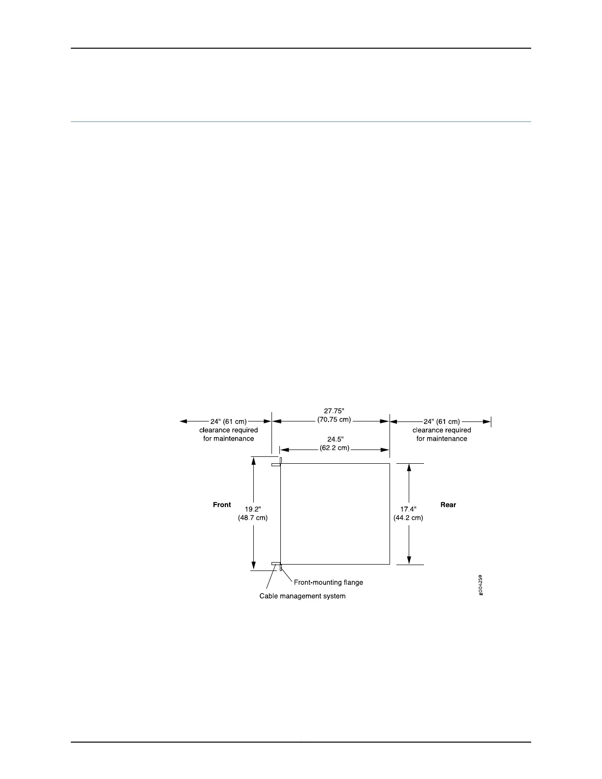
rack (see Figure 41 on page 125):
•
For the cooling system to function properly, the airflow around the chassis must be
unrestricted. Allow at least 8 in. (20.3 cm) of clearance between side-cooled routers.
Allow 5.5 in. (14 cm) between the side of the chassis and any non-heat-producing
surface such as a wall.
•
For service personnel to remove and install hardware components, there must be
adequate space at the front and back of the router. At least 24 in. (61 cm) is required
both in front of and behind the router. NEBS GR-63 recommends that you allow at
least 30 in. (72.6 cm) in front of the rack and 24 in. (61.0 cm) behind the rack.
Airflow must always be from front to back with respect to the rack. If the device has
side to rear airflow, then provisions must be made to ensure that fresh air from the
front of the rack is supplied to the inlets, and exhaust exits the rear of the rack. The
device must not interfere with the cooling of other systems in the rack. Fillers must be
used as appropriate in the rack to ensure there is no recirculation of heated exhaust
air back to the front of the rack. Care must also be taken around cables to ensure that
no leakage of air in situations where recirculation may result.
Figure 41: Clearance Requirements for Airflow and Hardware Maintenance
for an MX480 Router Chassis
Related
Documentation
MX480 Site Preparation Checklist on page 121•
• Installation Safety Warnings for Juniper Networks Devices
125Copyright © 2017, Juniper Networks, Inc.
Chapter 9: Preparation Overview