3-24 Service Manual
4023-001
• The Configuration ID is the only diagnostic function displayed
when the diagnostics mode is entered. This remains true until a
valid ID is entered.
Setting the Printhead Loop Adjustment
1. Enter the Diagnostic mode. See “Diagnostics Mode” on
page 3-1.
2. Select [PRINTER SETUP].
3. Select [Loop Adjustment].
4. Select [Tray 1], [Tray 2-4], or [Duplex Feeder].
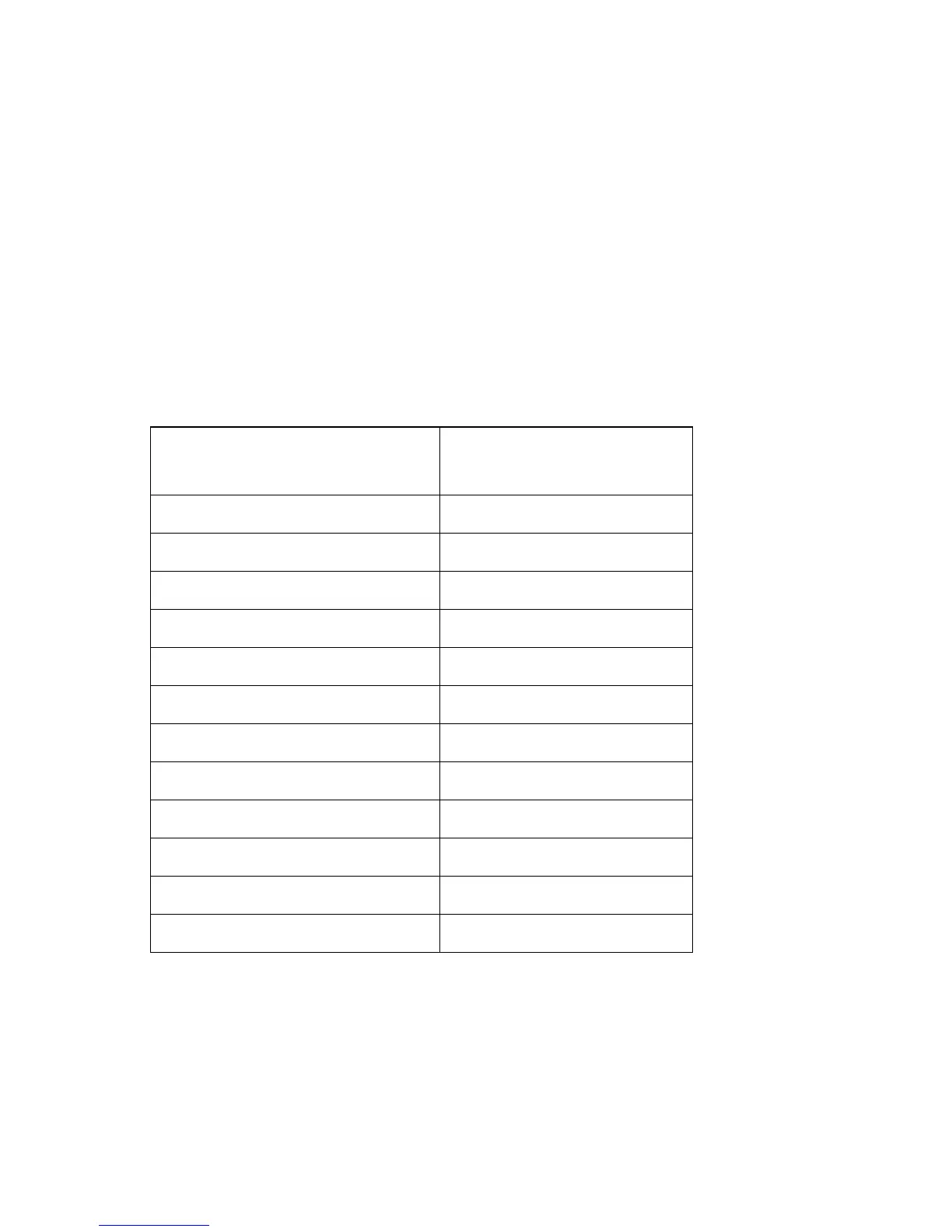
5. Set the selected input source to one of the following:
Setting Displayed on Panel
Engine Status Byte
(with bit 0 masked)
=Small - 0.0 mm* 0x00
=Small - 1.0 mm 0x02
=Small - 1.9 mm 0x04
=Small - 2.9 mm 0x06
=Small - 3.8 mm 0x08
=Small - 4.8 mm 0x0A
=Big - 0.0 mm 0x40
=Big - 1.0 mm 0x42
=Big - 1.9 mm 0x44
=Big - 2.9 mm 0x46
=Big - 3.8 mm 0x48
=Big - 4.8 mm 0x4A