215184 168 Revision A
Figure 5.27: Lifting Angle
22. Remove nuts at lifting angle locations and remove
angles (A).
23. Retrieve hold-down parts and hardware from bag attached to cutterbar and proceed to the appropriate step for your
equipment:
• For double-reel headers with formed hold-downs, refer to Step 24, page 168.
• For double-reel headers with forged hold-downs, refer to Step 25, page 168.
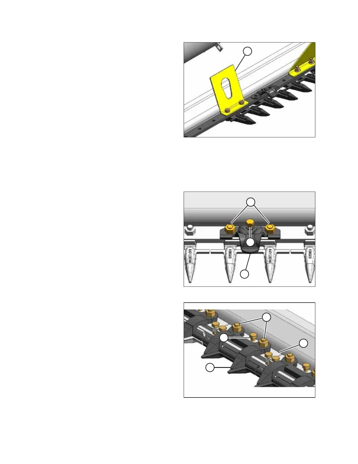
Figure 5.28: Pointed Guard
Double-reel headers
24. Install formed hold-downs as follows:
a. Position cutterbar wearplates on cutterbar and install
with 7/16 x 2-1/2 in. long carriage bolts (not shown).
b. Place hold-down (A) on cutterbar as shown and secure
with existing nuts (B). Adjuster bolt (C) should NOT
require adjusting.
c. Torque nuts to 72 Nm (53 lbf∙ft).
Figure 5.29: Stub Guard
Double-reel headers
25. Install forged hold-downs (stub guard only) as follows:
a. Position cutterbar wearplates on cutterbar and install
with 7/16 in. x 2-1/2 in. long carriage bolts (not
shown).
b. Place adjuster plate (D) and hold-down (A) on cutterbar
as shown and secure with 7/16 in. hex nuts (B).
Adjuster bolt (C) should NOT require adjusting.
c. Torque nuts to 72 Nm (53 lbf·ft).
UNLOADING HEADER AT DEALER