5.2 European Standards
162 SIEPCYEUOQ2V01A Q2V Technical Manual
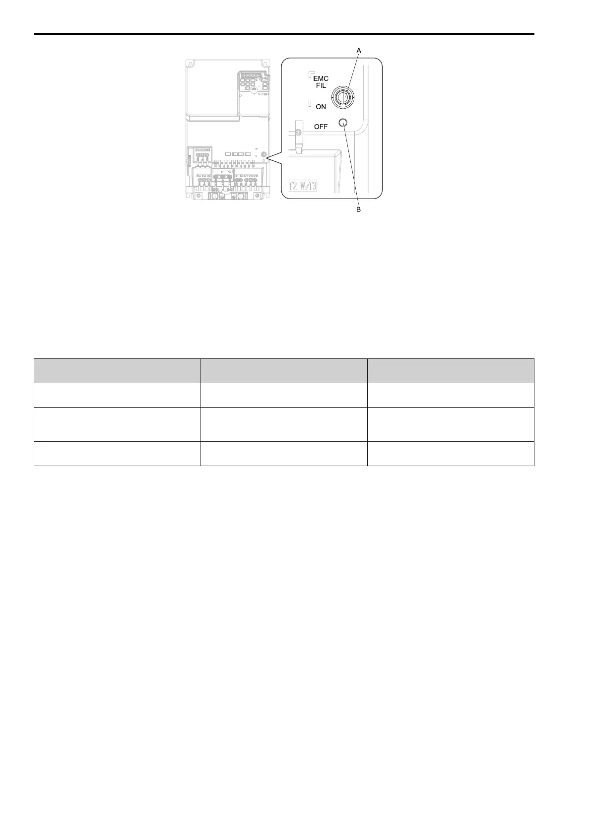
A - SW (ON) B - SW (OFF)
Figure 5.10 EMC Filter Switch Location (Models 2030E - 2082E, 4018E - 4060E)
NOTICE: Only use the screws specified in this manual. If you use screws that are not approved, it can cause damage to the
drive.
EMC Filter Switch Screws
If you lose an EMC filter switch screw, use this information to find the correct replacement screw and install the
new screw with the correct tightening torque.
Table 5.9 Screw Sizes and Tightening Torques
Model Screw Size
Tightening Torque
N∙m (in∙lb)
2001 - 2006
B001 - B004
M3 × 16
0.5 - 0.7
(4.4 - 6.2)
2010 - 2021
B006 - B012
4001 - 4012
M3 × 20
0.5 - 0.7
(4.4 - 6.2)
2030 - 2082
4018 - 4060
M4 × 20
1.0 - 1.3
(8.9 - 11.5)
■ Installing the External EMC Noise Filter
Drive models 2xxxA, BxxxA, and 4xxxA must meet conditions in this section to comply with EN 61800-3.
Connect an EMC noise filter to the input side (primary side) that complies with European standards as specified
by Yaskawa. Refer to External EMC Noise Filter Selection on page 164 to select the correct EMC noise filter.
Use this procedure to install an EMC noise filter to make equipment and devices added to the drive comply with
the EMC Directive.
1. Install the drive and EMC noise filter on the same grounded metal plate.
2. Wire the drive and motor.

 Loading...


