11.17 Parameters that Change from the Default Settings with A1-02 [Control Method]
404 SIEPCYEUOQ2V01A Q2V Technical Manual
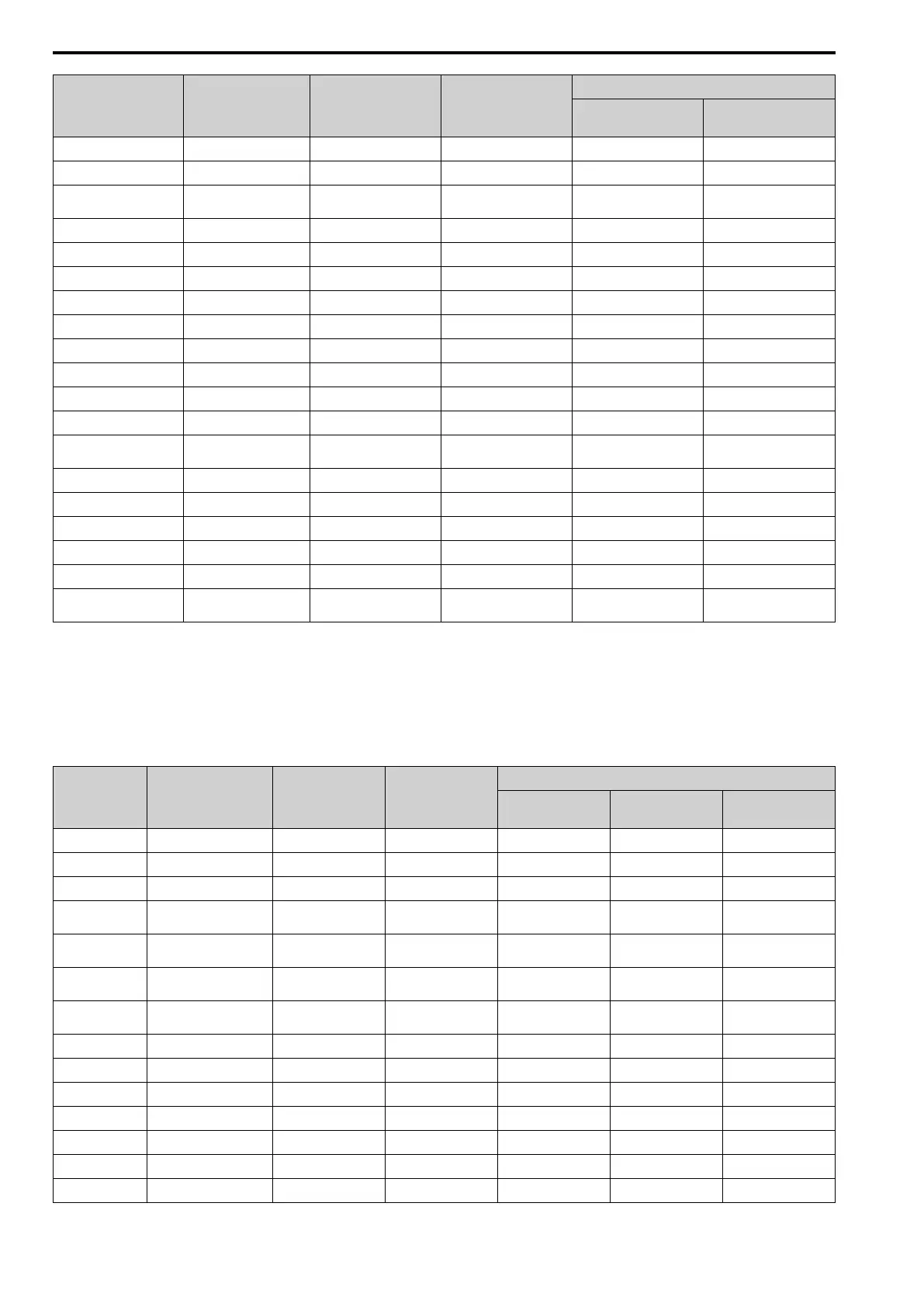
No. Name Range Unit
Control Method (A1-02 Setting)
V/f
(0)
OLV
(2)
E1-10 Min Output Voltage 0.0 - 255.0
*5
0.1 V 9.0
*4
2.0
F1-09 Overspeed Delay Time 0.0 - 2.0 0.1 s - -
L1-01
Motor Cool Type for OL1
Calc
0 - 4 1 1 1
L2-31 KEB StartV Offset Level 0 - 100
*5
1 V 0 0
L3-05 StallP@RUN Enable 0 - 3 1 1 1
L3-20 DCBus VoltAdj Gain 0.00 - 5.00 0.01 1.00 0.30
L3-21 OVSup Acc/Dec Gain 0.10 - 10.00 0.01 1.00 1.00
L3-36 VibSup Gain@Accel 0.0 - 100.0 0.1 10.0 20.0
L4-01 SpAgree Det.Level 0.0 - 400.0
*6
0.1 0.0 Hz 0.0 Hz
L4-02 SpAgree Det.Width 0.0 - 20.0 0.1 2.0 Hz 2.0 Hz
L4-03 SpAgree Det.Level(+/-) -400.0 - +400.0
*7
0.1 0.0 Hz 0.0 Hz
L4-04 SpAgree Det.Width(+/-) 0.0 - 20.0 0.1 2.0 Hz 2.0 Hz
L8-40
Carrier Red Off-Delay
Time
0.00 - 2.00 0.01 s 0.50 0.50
L8-90 STPo Detect Level 0 - 5000 1 - -
n5-04 Speed Response Frequency 0.00 - 500.00 0.00 Hz - -
n8-35 InitRotorPos Selection 0 - 2 1 - -
n8-51 Ac/Dec Pull-In Current 0 - 200% 1 0 0
o1-03 FrqDisplay Unit Selection 0 - 3 1 0 0
o1-04
V/f Pattern Unit for
Display
0 - 1 1 - -
*1 The default setting changes when the setting for o2-04 [Drive KVA Selection] changes.
*2 The default setting changes when the setting of C6-01 [ND/HD Duty Selection] changes.
*3 The setting range changes when the setting of E5-01 [PM Mot Code Selection] changes when A1-02 = 5 [PM OLVector].
*4 The default setting changes when the drive model and E1-03 [V/f Pattern Selection] change.
*5 This is the value for 200 V class drives. Double the value for 400 V class drives.
*6 When A1-02 = 5 [PM OLVector], the maximum value of the setting range is 100.0.
*7 When A1-02 = 5 [PM OLVector], the setting range is -100.0 to +100.0.
Table 11.2 A1-02 = 5, 6, 8 [PM OLVector, PM AOLVector, EZ Vector]
No. Name Range Unit
Control Method (A1-02 Setting)
OLV/PM
(5)
AOLV/PM
(6)
EZOLV
(8)
b2-01 ZSpd/DCI Threshold 0.0 - 10.0 0.1 0.5 Hz 1.0% 0.5Hz
b2-04 DCInj Time@Stop 0.00 - 10.00 0.01 s 0.00 0.00 0.00
b3-01 SpSrch@Start Selection 0 - 1 1 0 0 0
b3-02
SpSrch Deactivation
Current
0 - 200 1% - - -
b3-08
Speed ACR PGain for
Estimation
0.00 - 6.00 0.01 0.30 0.30 0.30
b3-09
Speed ACR ITime for
Estimation
0.0 - 1000.0 0.1 ms 4.0 4.0 4.0
b3-14
Speed Bi-Directional
Search
0 - 1 1 - - 0
b5-15 Sleep Start Level 0.0 - 400.0
*1
0.1 0.0 Hz 0.0% 0.0%
b6-01 Dwell Ref.@Start 0.0 - 400.0
*1
0.1 0.0 Hz 0.0% 0.0%
b6-03 Dwell Ref@Stop 0.0 - 400.0
*1
0.1 0.0 Hz 0.0% 0.0%
b8-02 eSave Ctrl Gain 0.0 - 10.0 0.1 - - -
b8-03 eSave Filter Time 0.00 - 10.00 0.01 s - - -
b8-19 eSave Search Frequency 10 - 300 1 Hz 100 100 20
C1-11 Ac/Dec Switch Frequency 0.0 - 400.0
*1
0.1 0.0 Hz 0.0% 0.0%

 Loading...


