Parameter List
11
11.17 Parameters that Change from the Default Settings with A1-02 [Control Method]
SIEPCYEUOQ2V01A Q2V Technical Manual 405
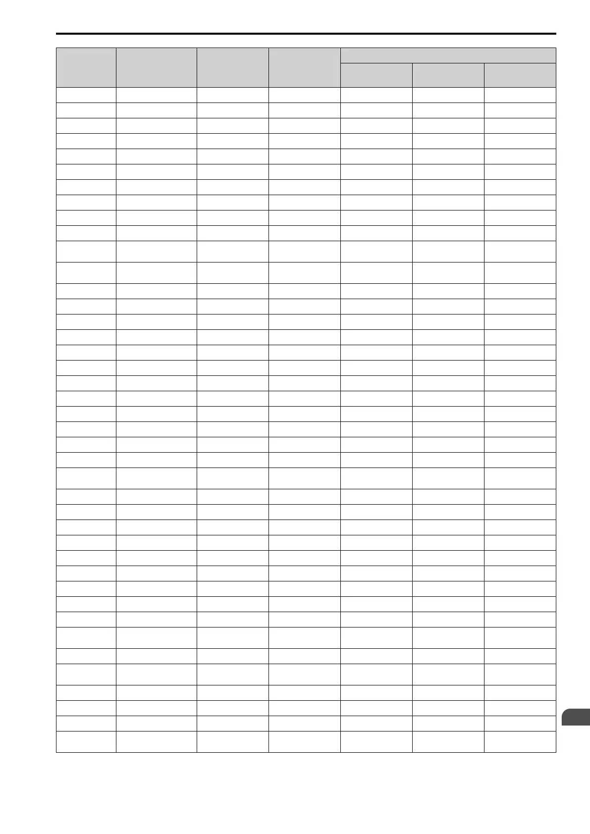
No. Name Range Unit
Control Method (A1-02 Setting)
OLV/PM
(5)
AOLV/PM
(6)
EZOLV
(8)
C2-01 Jerk@Start of Accel 0.00 - 10.00 0.01 s 1.00 0.20 1.00
C3-01 Slip Comp Gain 0.0 - 2.5 0.1 - - 0
C3-02 Slip Comp Delay Time 0 - 10000 1 ms - - 200
C4-01 Trq Comp Gain 0.00 - 2.50 0.01 0.00 - 0.00
C4-02 Trq Comp Delay Time 0 - 10000 1 ms 100 - 100
C5-01 ASR PGain 1 0.00 - 300.00 0.01 10.00 10.00 10.00
C5-02 ASR ITime 1 0.000 - 60.000 0.001 s 0.500 0.500 0.500
C5-03 ASR PGain 2 0.00 - 300.00 0.01 - 10.00 10.00
C5-04 AASR ITime 2 0.000 - 10.000 0.001 s - 0.500 0.500
C5-06 ASR Delay Time 0.000 - 0.500 0.001 s - 0.016 0.004
C5-07
ASR Gain Switch
Frequency
0.0 - 400.0
*1
0.1 0.0Hz 0.0% 0.0%
C6-02
Carrier Frequency
Selection
1 - F 1 2 2 2
d3-01 Jump Frequency 1 0.0 - 400.0
*1
0.1 0.0 Hz 0.0% 0.0%
d3-02 Jump Frequency 2 0.0 - 400.0
*1
0.1 0.0 Hz 0.0% 0.0%
d3-03 Jump Frequency 3 0.0 - 400.0
*1
0.1 0.0 Hz 0.0 % 0.0 %
d3-04 Jump Frequency Width 0.0 - 20.0
*2
0.1 1.0 Hz 1.0 % 1.0 %
E1-04 Max Output Frequency 40.0 - 400.0
*3
0.1 Hz Determined by E5-01 Determined by E5-01 Determined by E5-01
E1-05 Max Output Voltage 0.0 - 255.0
*4
0.1 V Determined by E5-01 Determined by E5-01 Determined by E5-01
E1-06 Base Frequency 0.0 - 400.0 0.1 Hz Determined by E5-01 Determined by E5-01 Determined by E5-01
E1-07 Mid A Frequency 0.0 - 400.0 0.1 Hz - - -
E1-08 Mid A Voltage 0.0 - 255.0
*4
0.1 V - - -
E1-09 Min Output Frequency 0.0 - 400.0 0.1 Hz Determined by E5-01 Determined by E5-01 Determined by E5-01
E1-10 Min Output Voltage 0.0 - 255.0
*4
0.1 V - - -
F1-09 Overspeed Delay Time 0.0 - 2.0 0.1 s - 0.0 -
L1-01
Motor Cool Type for OL1
Calc
0 - 4 1 4 4 Determined by E9-01
L2-31 KEB StartV Offset Level 0 - 100
*4
1 V 50 50 50
L3-05 StallP@RUN Enable 0 - 3 1 1 - 3
L3-20 DCBus VoltAdj Gain 0.00 - 5.00 0.01 0.65 0.65 0.65
L3-21 OVSup Acc/Dec Gain 0.10 - 10.00 0.01 1.00 1.00 1.00
L3-36 VibSup Gain@Accel 0.0 - 100.0 0.1 - - -
L4-01 SpAgree Det.Level 0.0 - 400.0
*1
0.1 0.0 Hz 0.0% 0.0%
L4-02 SpAgree Det.Width 0.0 - 20.0
*2
0.1 2.0 Hz 4.0% 4.0%
L4-03 SpAgree Det.Level(+/-) -400.0 - +400.0
*5
0.1 0.0 Hz 0.0% 0.0%
L4-04 SpAgree Det.Width(+/-) 0.0 - 20.0
*2
0.1 2.0 Hz 4.0% 4.0%
L8-40
Carrier Red Off-Delay
Time
0.00 - 2.00 0.01 s 0.00 0.00 0.00
L8-90 STPo Detect Level 0 - 5000 1 0 80 -
n5-04
Speed Response
Frequency
0.00 - 500.00 0.00 Hz - 20.00 -
n8-35 InitRotorPos Selection 0 - 2 1 0 1 -
n8-51 Ac/Dec Pull-In Current 0 - 200% 1 50% 0 80%
o1-03 FrqDisplay Unit Selection 0 - 3 1 0 1 1
o1-04
V/f Pattern Unit for
Display
0 - 1 1 - 1 -
*1 The setting range is 0.0 to 100.0 when A1-02 = 6 [PM AOLVector].
*2 The setting range is 0.0 to 40.0 when A1-02 = 6 [PM AOLVector].

 Loading...


