12.2 b: APPLICATION
468 SIEPCYEUOQ2V01A Q2V Technical Manual
Use Table 12.14 to select how the feedback signal is input to the drive for PID control.
Table 12.14 PID Feedback Input Method
PID Feedback Input Method Setting Value
MFAI terminal AI1 Set H3-02 = F [PID Fbk].
MFAI terminal AI2 Set H3-10 = F.
Pulse train input terminal DI Set H6-01 = 1 [PIDFbk Value].
• Use two signals, and use the difference between those signals as the feedback signal.
The drive uses two feedback signals, and the difference between those signals becomes the deviation.
Use Table 12.15 to select how the second feedback value is input to the drive. The drive calculates the deviation
of the second feedback value. Set H3-02 or H3-10 = 11 [AI1 Function Selection or AI2 Function Selection =
Diff PIDFbk] to enable the second feedback signal used to calculated the deviation.
Table 12.15 PID Differential Feedback Input Method
PID Differential Feedback Input Method Setting Value
MFAI terminal AI1 Set H3-02 = 11 [Diff PIDFbk].
MFAI terminal AI2 Set H3-10 = 11.
Note:
If you set H3-02 and H3-10 = 11, it will trigger oPE07 [Analog Input Selection Error].
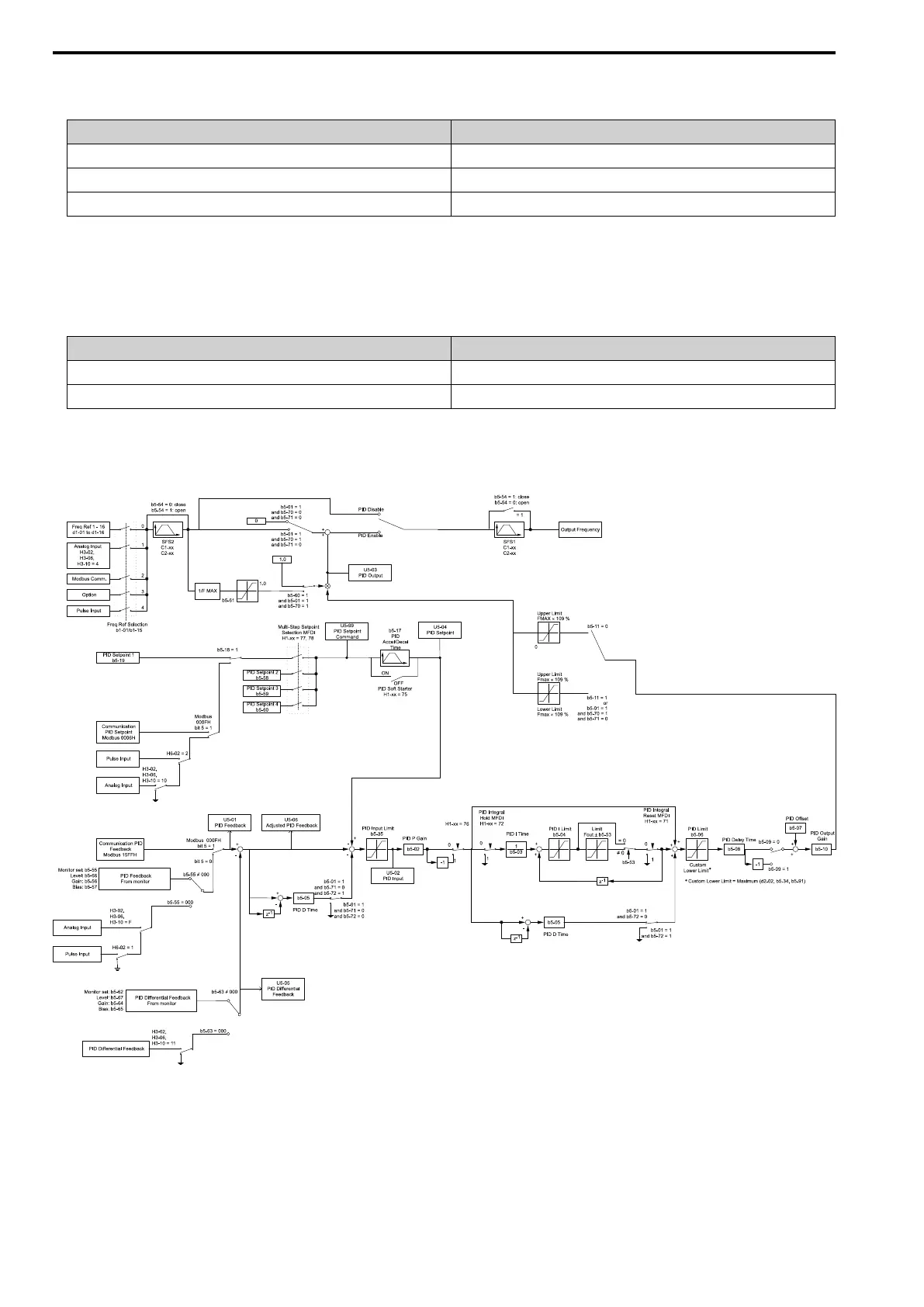
■ PID Control Block Diagram
Figure 12.29 PID Control Block Diagram
■ PID Feedback Loss Detection
The PID feedback loss detection function detects broken sensors and defective wiring between the drive and
sensors.

 Loading...


