Parameter Details
12
12.5 E: MOTOR
SIEPCYEUOQ2V01A Q2V Technical Manual 525
Note:
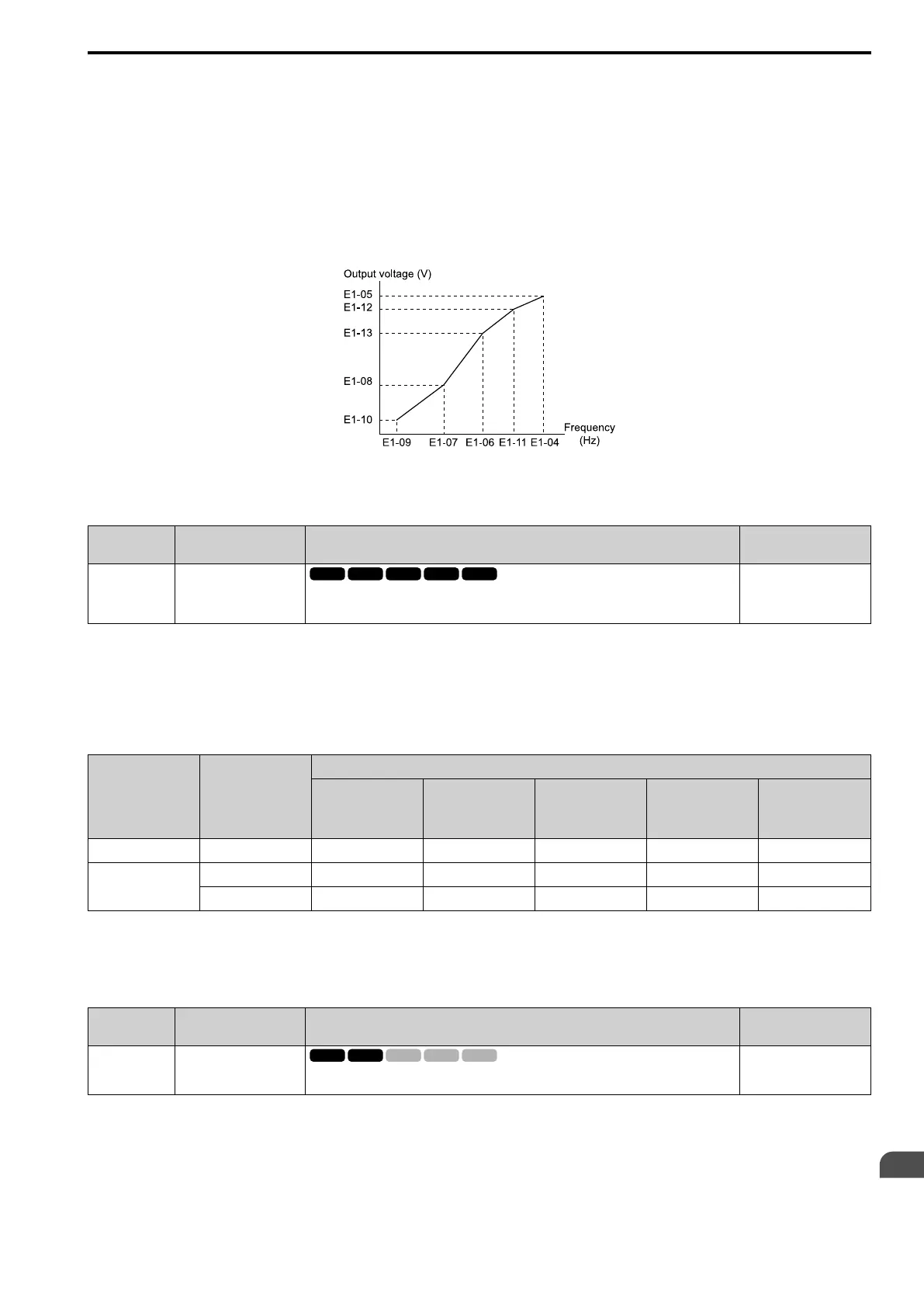
Be aware of the following points when manually setting V/f patterns.
• To set linear V/f characteristics at frequencies lower than E1-06 [Base Frequency], set E1-07 = E1-09 [Mid A Frequency = Min Output
Frequency]. In this application, the drive ignores E1-08 [Mid A Voltage].
• Set the five frequencies as specified by these rules: Incorrect settings will cause oPE10 [V/f Data Setting Error].
E1-09 ≤ E1-07 < E1-06 ≤ E1-11 ≤ E1-04 [Min Output Frequency ≤ Mid A Frequency < Base Frequency ≤ Mid B Frequency ≤ Max
Output Frequency]
• Setting E1-11 = 0 [Mid B Frequency = 0 Hz] disables E1-12 [Min Output Voltage]. Ensure that the four frequencies are set according
to the following rules;
E1-09 ≤ E1-07 < E1-06 ≤ E1-04
• When you use A1-03 [Init Parameters] to initialize the drive, it will not reset E1-03.
Figure 12.60 V/f Pattern
■ E1-01: Input AC Supply Voltage
No.
(Hex.)
Name Description
Default
(Range)
E1-01
(0300)
Input AC Supply Voltage
Sets the drive input voltage.
200 V Class: 230 V, 400 V:
400 V
(200 V Class: 155 to 255 V,
400 V Class: 310 to 510 V)
NOTICE: Set parameter E1-01 to align with the drive input voltage (not motor voltage). If this parameter is incorrect, the
protective functions of the drive will not operate correctly and it can cause damage to the drive.
Values Related to the Drive Input Voltage
The value set in E1-01 is the base value that the drive uses for the motor protective functions in Table 12.29. With
a 400 V class drive, the detection level changes for some motor protective functions.
Table 12.29 Values Related to the Drive Input Voltage
Voltage E1-01 Setting
Approximate Values
ov Detection Level
BTR Operation
Level
(rr Detection Level)
*1
L2-05
[E1-01: UV
Detection Lvl (Uv1)]
L2-11
[KEB DC Volt
Setpoint]
L3-17
[DCBus Regul.
Level]
200 V class All settings 410 V 394 V 190 V 260 V 375 V
400 V class
Setting value ≥ 400 V 820 V 788 V 380 V 500 V 750 V
Setting value < 400 V 820 V 788 V 350 V 460 V 750 V
*1 This is the protection function enabled in drives with built-in braking transistors. These values show the level that will trigger the
built-in braking transistor. Refer to ““Braking Unit, Braking Resistor Unit Instruction Manual (TOBPC72060001)”” for more
information.
■ E1-03: V/f Pattern Selection
No.
(Hex.)
Name Description
Default
(Range)
E1-03
(0302)
V/f Pattern Selection
Sets the V/f pattern for the drive and motor. You can use one of the preset patterns or you can
make a custom pattern.
F
(Determined by A1-02)
Note:
• When A1-02 = 2 [Control Method = OLVector], settings 0 to E are not available.
• Set the correct V/f pattern for the application and operation area. An incorrect V/f pattern can decrease motor torque and increase
current from overexcitation.
• Parameter A1-03 [Init Parameters] will not reset the value of E1-03.
0 : CT_50-50Hzmax

 Loading...


