Parameter Details
12
12.7 H: TERMINALS
SIEPCYEUOQ2V01A Q2V Technical Manual 597
Note:
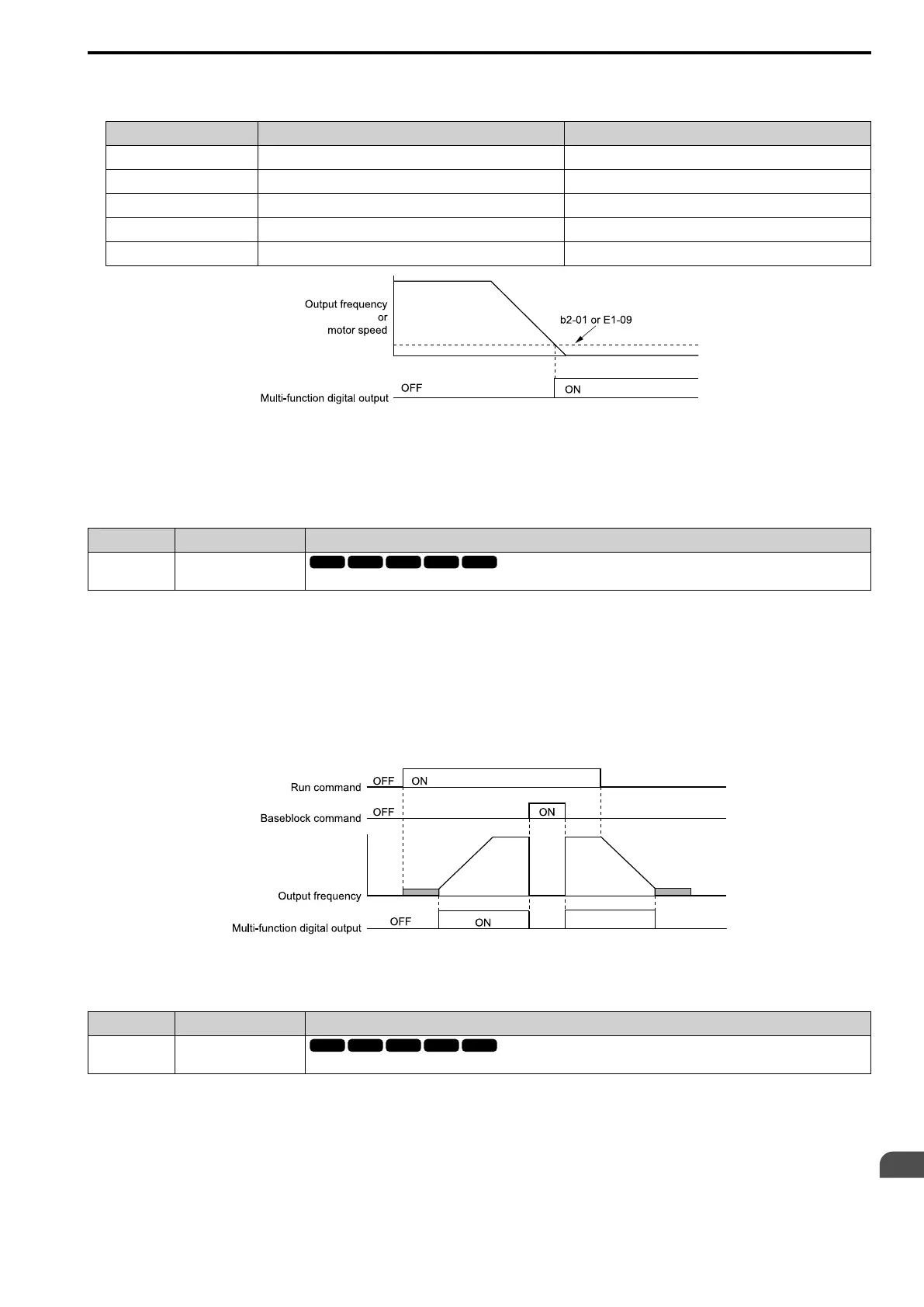
Parameter A1-02 [Control Method] selects which parameter is the reference.
A1-02 Setting Control Method Selection Parameter Used as the Reference
0 V/f Control E1-09
2 OLVector b2-01
5 PM OLVector E1-09
6 PM AOLVector E1-09
8 EZ Vector E1-09
Figure 12.78 Zero Speed Time Chart
ON : Output frequency < value of E1-09 or b2-01.
OFF : Output frequency ≥ value of E1-09 or b2-01.
■ B: @FreqOutput
Setting Value Function Description
B @FreqOutput
The terminal activates when the drive outputs frequency.
ON : The drive outputs frequency.
OFF : The drive does not output frequency.
Note:
The terminal deactivates in these conditions:
• During Stop
• During baseblock
• During DC Injection Braking (initial excitation)
• During Short Circuit Braking
Figure 12.79 Active Frequency Output Time Chart
■ D: LO/RE Status
Setting Value Function Description
D LO/RE Status
The terminal activates when the Run command source or frequency reference source is LOCAL.
ON : LOCAL
The keypad is the Run command source or the frequency reference source.
OFF : REMOTE
The Run command source or frequency reference source is an external source set with b1-01 [Freq. Ref. Sel. 1],
b1-15 [Freq. Ref. Sel. 2], b1-02 [Run Comm. Sel 1], or b1-16 [Run Comm. Sel 2].

 Loading...


