6 - 39
6 Basic Parameter Settings
High-function General-purpose Inverter RX2 Series User’s Manual
6-4 Frequency Command Settings
6
6-4-9 Case where Command Is Given with Multi-Step Speed
Precautions for Correct Use
• For the binary operation, idling time to wait for a terminal input to be given can be set in the
Multistage input determination time [CA-55]. This can prevent transition during terminal
switching.
• Data are fixed after the time specified in [CA-55] passes with no change in the input. Input
response would be slow if the determination time is set to be large.
• For the command frequency of the 0th speed, the command designated in the Main speed
input source selection, 1st-motor [AA101] is used. The above table is for [AA101]=07.
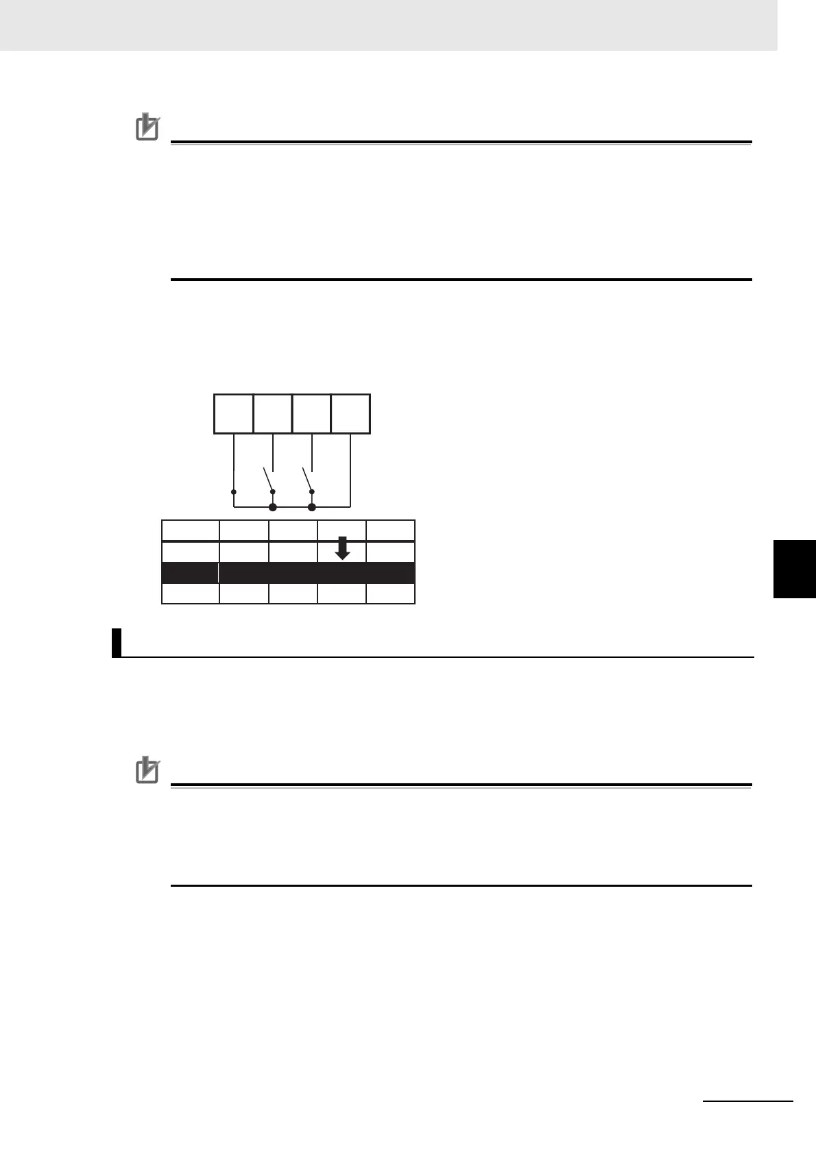
Ex.) 2nd speed is effective.
In this case we have [CA-06]=003 (CF1) and [CA-07]=004 (CF2).
No assignment is made for 005 (CF3) and 006 (CF4).
Only the input terminal No. 7 (CF2) is ON.
Multi-step speeds of 0th to 7th speeds can be chosen by assigning 007-013 ([SF1]-[SF7]) to the input
terminals selection 1-9, A, and B [CA-01]-[CA-11].
The frequency setting of [SF1]-[SF7] should be made to the multi-step speeds of 1st to 7th speeds
([Ab-11]-[Ab-17]).
Precautions for Correct Use
• If multiple terminals are made ON simultaneously, the one with smaller number has priority.
“-” in the table indicates that a frequency is chosen independently from ON/OFF state of the
terminals.
• For the command frequency of the 0th speed, the command designated in the main speed
selection [AA101] is used. The following table is for [AA101]=07.
Bit Operation (Maximum 8-speed Command: [Ab-03]=01)
Multi-step
speed
Input terminal
1st speed
2nd speed
3rd speed
 Loading...


