8 - 11
8 Applied Settings
High-function General-purpose Inverter RX2 Series User’s Manual
8-1 PID Control
8
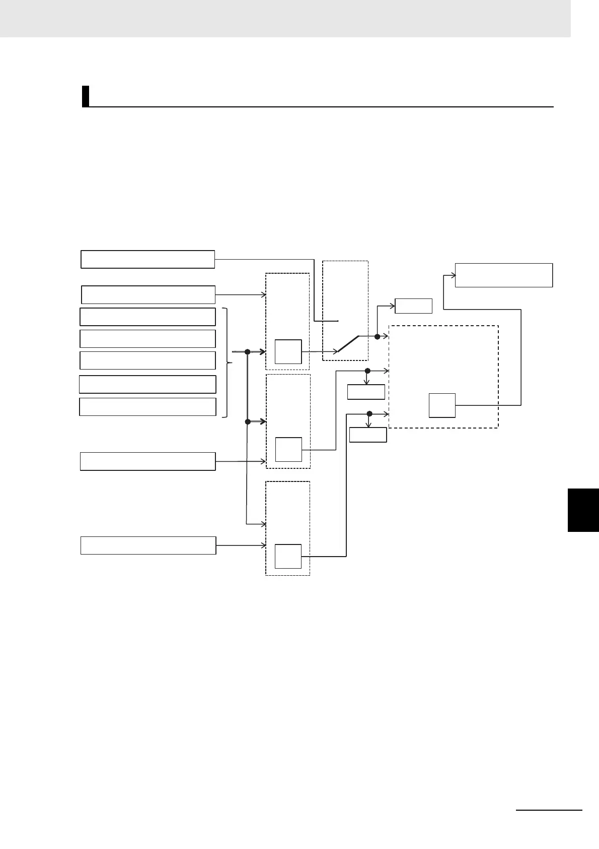
8-1-2 PID Parameter and Block Diagram
Select PID1 target value.
In the case of setting target value with one input, set 00: None to [AH-42]/[AH-46] and 01: Add to
[AH-50] to disable the input destination 2/3.
Calculation result of operator [AH-50] will be restricted in a range of -100.00 to 100.00 (%).
When Operator [AH-50] is 01 to 04
When 01 to 04 is selected in operator [AH-50], calculation is targeted to target value 1 and target
value 2.
PID1 Target Value Selection
[AH-07]
[SVC1-4]
+(01), -(02), x(03), ÷ (04)
[AH-42]
(01 to 06,
07,08,
12,13)
[AH-12] to [AH-40]
[AH-10]
[AH-44]
07
00
[FA-30]
(01 to 06,
07,08,
12,13)
[FA-34]
[AH-46]
00
(01 to 06,
07,08,
12,13)
[AH-48]
[FA-32]
051 to 054
Multi-layer target value 1 to 15
Input
destination 1
Input
destination 2
Input
destination 3
Calcul
ation
PID1 target value [db-42]
PID1 setting 1 (07)
Analog input Ai1 to Ai6 (01 to 06)
RS 485 communication (08)
Option 1 to 3 (09 to 11)
Pulse train input (main unit) (12)
Pulse train input (PG Option Unit) (13)
PID1 setting 2 (07)
PID1 setting 3 (07)
Operator [AH-50]
Calculation of target values 1
and 2
(00: Disable)
(00: Disable)
Multi-layer
target
Input

 Loading...


