8 - 15
8 Applied Settings
High-function General-purpose Inverter RX2 Series User’s Manual
8-1 PID Control
8
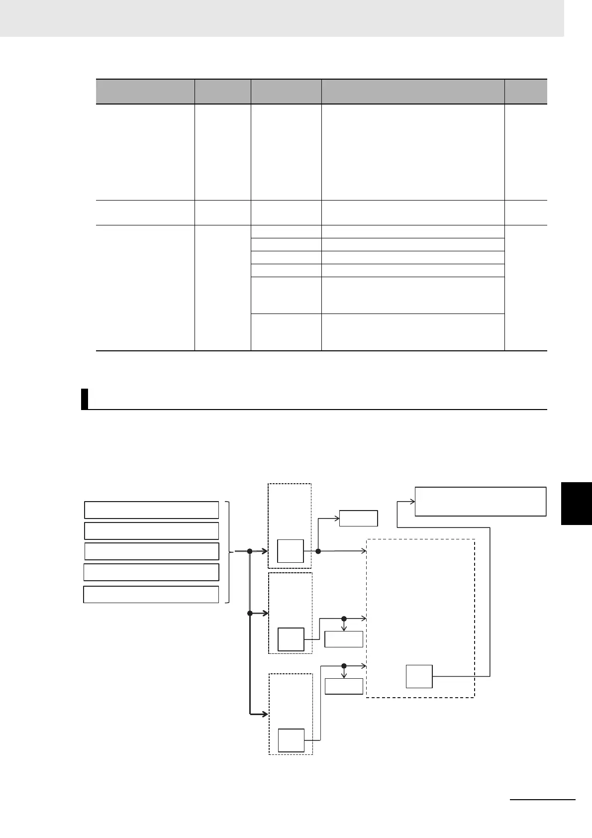
8-1-2 PID Parameter and Block Diagram
This selects PID1 feedback data.
In the case of setting feedback data with one input, set 00: None to [AH-52]/[AH-53] and 01: Add to
[AH-54] to disable the input destination 2/3.
Calculation result of operator [AH-54] will be restricted in a range of -100.00 to 100.00 (%).
Input source selection
of Set-point 3 for PID1
[AH-46] 00 to 13
00: Invalid, 01: Ai1-L input, 02: Ai2-L input,
03: Ai3-L input, 04: (Reserved),
05: (Reserved), 06: (Reserved),
07: Parameter setting [AH-48],
08: RS 485 communication, 09: Option 1,
10: Option 2, 11: Option 3,
12: Pulse train input (main unit),
13: Pulse train input (option)
00
Set-point 3 setting for
PID1
[AH-48]
0.00 to
100.00[%]
*1
Is a parameter set value. 0.00
Calculation symbol
selection of Set-point 1
for PID1
[AH-50]
01 (Target value 1) + (Target value 2)
01
02 (Target value 1) - (Target value 2)
03 (Target value 1) x (Target value 2)
04 (Target value 1) / (Target value 2)
05
Minimum of deviation 1 (Target value 1 - FB
1), deviation 2 (Target value 2 - FB 2), and
deviation 3 (Target value 3 - FB 1)
06
Maximum of deviation 1 (Target value 1 - FB
1), deviation 2 (Target value 2 - FB 2), and
deviation 3 (Target value 3 - FB 1)
*1. Data range varies depending on the data from [AH-04] to [AH-06].
Selection of PID1 Feedback Data
Item Parameter Data Description
Default
data
[AH-51]
[AH-52]
(01 to 06,
08,12,13)
(01 to 06,
08,12,13)
01
00
[db-30]
[db-32]
[AH-53]
00
(01 to 06,
08,12,13)
[db-34]
Analog input Ai1 to Ai3 (01 to 03)
PID1 feedback data
[db-44]
Calcul
ation
Operator [AH-54]
Calculation of FB1 and FB2
+(01), -(02), x(03), ÷(04)
Square root of FB1 (05)
Square root of FB2 (06)
Square root of FB1 - FB2 (07)
Average of FB1 to FB3 (08)
Minimum of FB1 to FB3 (09)
Maximum of FB1 to FB3 (10)
Input
destination 3
(00: Disable)
Input
destination 1
Input
destination 2
RS 485 communication (08)
Option 1 to 3 (09 to 11)
Pulse train input (main unit) (12)
Pulse train input (option) (13)
(00: Disable)
 Loading...


