C - 35
Appendices C Table of Parameters
High-function General-purpose Inverter RX2 Series User’s Manual
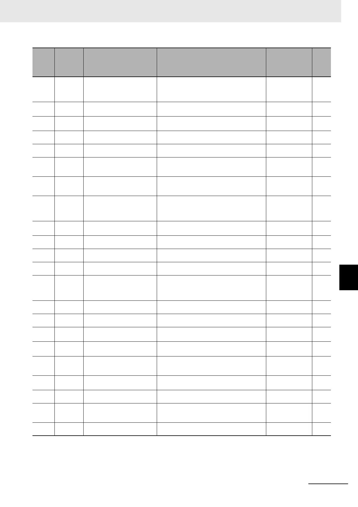
C-3 Parameter List
C
bA-30 -
Deceleration-stop at power fail-
ure
00 (Disabled)/
01 (Enabled: deceleration stop)/
02 (Enabled: no recovery)/
03 (Enabled: with recovery)
00
bA-31 ○
Decel-stop at power failure
starting voltage
(200 V class) 0.0 to 410.0 (V)
(400 V class) 0.0 to 820.0 (V)
(200 V class) 220.0
(400 V class) 440.0
bA-32 ○
Decel-stop at power failure con-
trol target level
(200 V class) 0.0 to 410.0 (V)
(400 V class) 0.0 to 820.0 (V)
(200 V class) 360.0
(400 V class) 720.0
bA-34 ○
Decel-stop at power failure
deceleration time
0.01 to 3600.00 (s) 1.00
bA-36 ○
Decel-stop at power failure freq.
width at deceleration start
0.00 to 10.00 (Hz) 0.00
bA-37 ○
Decel-stop at power failure
DC-bus voltage constant control
P-gain
0.00 to 5.00 0.20
bA-38 ○
Decel-stop at power failure
DC-bus voltage constant control
I-gain
0.00 to 150.00 (s) 1.00
bA140 ○
Over-voltage suppression
enable, 1st-motor
00 (Disabled)/
01 (DC voltage constant deceleration)
02 (Acceleration only at deceleration)/
03 (Acceleration at constant speed/deceleration)
00
bA141 ○
Over-voltage suppression active
level, 1st-motor
(200 V class) 330.0 to 400.0 (V)
(400 V class) 660.0 to 800.0 (V)
(200 V class) 380.0
(400 V class) 760.0
bA142 ○
Over-voltage suppression
action time, 1st-motor
0.00 to 3600.00 (s) 1.00
bA144 ○
DC bus constant control propor-
tional gain, 1st-motor
0.00 to 5.00 0.20
bA145 ○
DC bus constant control integral
gain, 1st-motor
0.00 to 150.00 (s) 1.00
bA146 ○
Over magnetization decelera-
tion function selection, 1st_mo-
tor
00 (Disabled)/01 (Regular operation)/
02 (Operation only at deceleration)/
03 (Level mode)/
04 (Level mode only at deceleration)
02
bA147 ○
Over magnetization output filter
time constant, 1st_motor
0.00 to 1.00(s) 0.30
bA148 ○
Over magnetization voltage
gain, 1st_motor
50 to 400 (%) 100
bA149 ○
Over magnetization level set-
ting, 1st_motor
(200 V class) 330.0 to 400.0 (V)
(400 V class) 660.0 to 800.0 (V)
(200 V class) 360.0
(400 V class) 720.0
bA-60 ○ Dynamic brake usage rate
0.0 to 10.0 ×
([bA-63]/minimum resistance)
2
(%)
*4
10.0
bA-61 - Dynamic brake selection
00 (Disabled)/
01 (Enabled: disabled at stop)/
02 (Enabled: enabled at stop)
00
bA-62 - Dynamic brake active level
(200 V class) 330.0 to 400.0 (V)
(400 V class) 660.0 to 800.0 (V)
(200 V class) 360.0
(400 V class) 720.0
bA-63 - Dynamic brake resister value
Minimum resistance to 600 (Ω)
*4
Minimum resis-
tance
*4
bA-70 ○
Cooling FAN control method
selection
00 (Always ON)/
01 (ON during operation)/
02 (Temperature dependent)
00
bA-71 -
Cooling FAN accumulation run-
ning time clear selection
00 (Disabled)/01 (Clear) 00
Code
Codes that
can be
changed
during
operation
Name Data range Initial value Note

 Loading...


