MI16-16 / Page 2 / 6
<QF7720955 rev 2>
PROCEDURE – STARTER REMOVAL AND INSTALLATION
Park vehicle safely, apply parking brake, stop the engine. Prior to working on the vehicle, set the
ignition switch to the OFF position, the battery master switch to the OFF position and trip the
main circuit breakers equipped with a trip button.
RISK OF ELECTRICAL SHOCK
1. The starter is connected to the batteries through master relay R1. If the ignition switch is in the OFF
position and the battery master switch (master cut-out) is set to the OFF position, there should not
be electrical power to the starter B (batt) terminal. However, a faulty master relay R1 could
eventually leave the battery power circuit closed, thus electrical power would be present at the
starter B terminal.
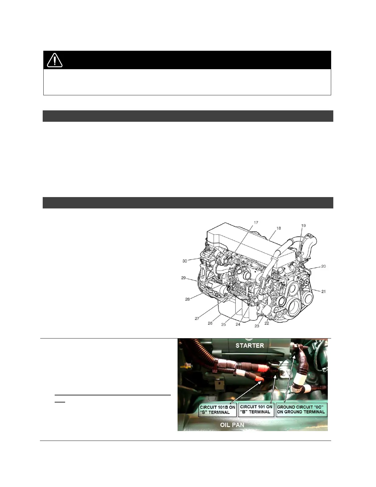
2. Using a voltmeter or multimeter, probe the starter B terminal and the ground terminal. Make sure
that the voltage reading is 0 volt prior disconnecting the starter cables (FIGURE 2).
STARTER REMOVAL
3. While proceeding from under the vehicle,
gain access to the starter (item 29 on
FIGURE 1) on the turbocharger side (street
side).
FIGURE 1: D13H ENGINE OVERVIEW, TURBO SIDE
4. On the starter, disconnect circuits 0C, 101
and 101B (see FIGURE 2). Properly clean
cable lugs as applicable using a brass
wire cup brush, a Scotch-Brite pad or an
emery cloth. Remove old Color Guard
Rubber Coating as much as possible.
IMPORTANT: keep hardware for later
use
 Loading...


