RF signal configuration
R&S
®
SMA100B
71User Manual 1178.3834.02 ─ 09
"Ref. Freq. Output"
Output of the internal reference signal, see Chapter 9.3, "Reference
output settings", on page 298 .
"Signal Valid" / "Signal Valid Neg."
Automatically generated output signal that identifies a valid signal
time (level and frequency) for all analog modulation signals.
For "Signal Valid Neg." (inverted), the output signal is low during the
valid signal time.
"Pulse In"
Input of an external pulse signal or input of external trigger/gate sig-
nal for the internal pulse generator (see Chapter 5.4.4, "Pulse gener-
ator", on page 98).
"Pulse Video"
Output of the internal pulse generator signal or the looped through
"Pulse Ext" pulse signal (video signal), see Chapter 5.4.1, "Pulse
modulation settings", on page 84.
Connector
Displays the assigned connector.
Show Connector
Accesses a dialog that displays the physical location of the selected connector on the
front/rear panel of the instrument.
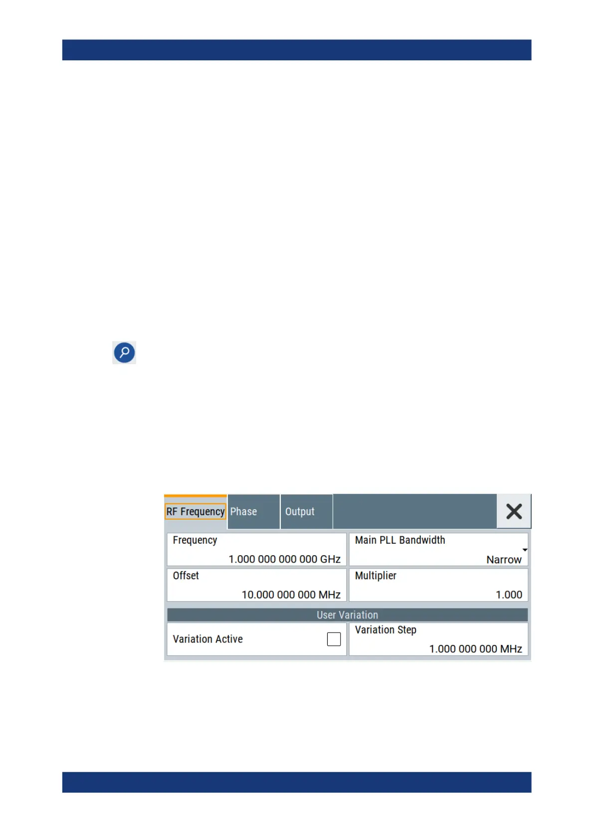
4.5 RF frequency settings
Access:
1. Select "Frequency" > "RF Frequency".
2. Observe the information on the home screen, "Frequency" tile.
RF frequency settings