6A-40 ENGINE REPAIR
NOTE:
Fitting the dial gauge and adjusting to zero are
necessary only to verify if the crankshaft moves while
the flywheel is replaced.
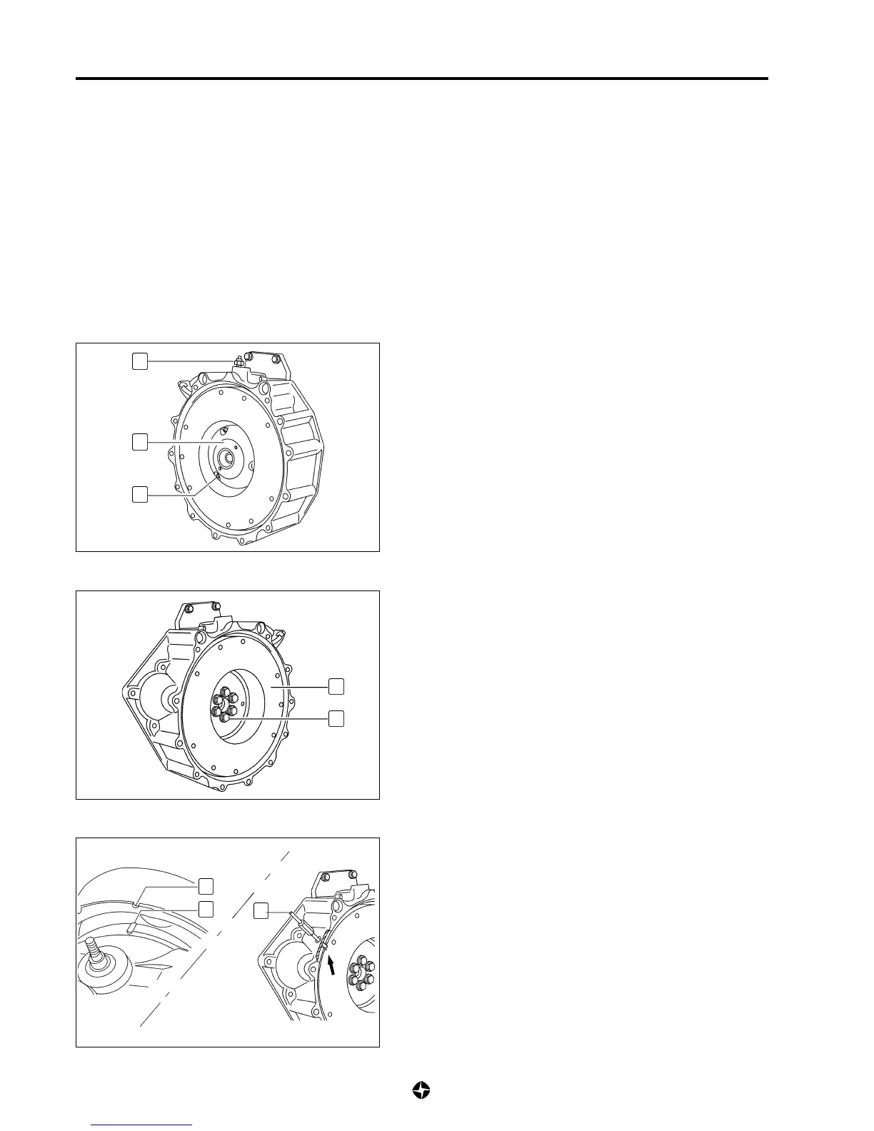
6) Remove:
• Gear box assembly (see 7A-9).
• Pressure plate and clutch disc assembly (see 7C-10).
7) Take away connector of r.p.m sensor (8) and remove sensor.
8) Block the possibility of flywheel rotation, remove screws (6)
fixing supporting rolling plate (5) of gear box primary axle
and remove plate.
9) Remove screws (7), withdraw tools blocking flywheel turning
as well as synchronising tool (C); remove flywheel (2).
NOTE:
If oil leaks through the back oil-seal from crankshaft
are detected, replace it (see 6A-47).
Installation
1) Align mark (A) of camshaft gear and mark (B) at lit. Ensure
that the dial gauge remain reading zero.
2) Install flywheel, placing its screws without tightening and
centre flywheel using tool (C) ref. 790965; in this position
(dial gauge in zero), block flywheel from turning and tighten
its screws to the specified torque in two steps.
If the dial gauge is not at zero, adjust it with small turning of
crankshaft before tightening flywheel.
Tightening torque for screws of flywheel:
• 1
st
step: With dynamometric tool: 5 ± 0,5 Kg-m (50 ± 5 Nm)
• 2
nd
step: Angular tightening: 90º ± 10º
2
7
5
6
C
A
B
8

 Loading...