ENGINE FUEL AND EMISSION CONTROL SYSTEM 6C-5
AIR INTAKE SYSTEM
The air intake system is made up of the following components:
• A dry air filter composed of a filter element to be replaced
periodically.
• A turbocharger which uses the exhaust gases to move a
high revolution turbine to send compressed air to the
cylinders. This incorporates a pressure limitation which
varies the turbine revolutions sending part straight to the
exhaust pipe when the overfeed air pressure reaches the
calibrated value.
Turbocharger is oiled using engine oil.
• An intercooler or heat interchanger, consisting of an air
radiator attached to a water radiator. Its function is to lower
the temperature of the air leaving the turbocharger before
entering the cylinders.
• An intake manifold which distributes the air sent from the
turbocharger to the cylinders. Attached to the intake ma-
nifold is a pipe to show the pressure generated within the
turbocharger to the LDA device (mechanical injection
engines).
932
1
7
8
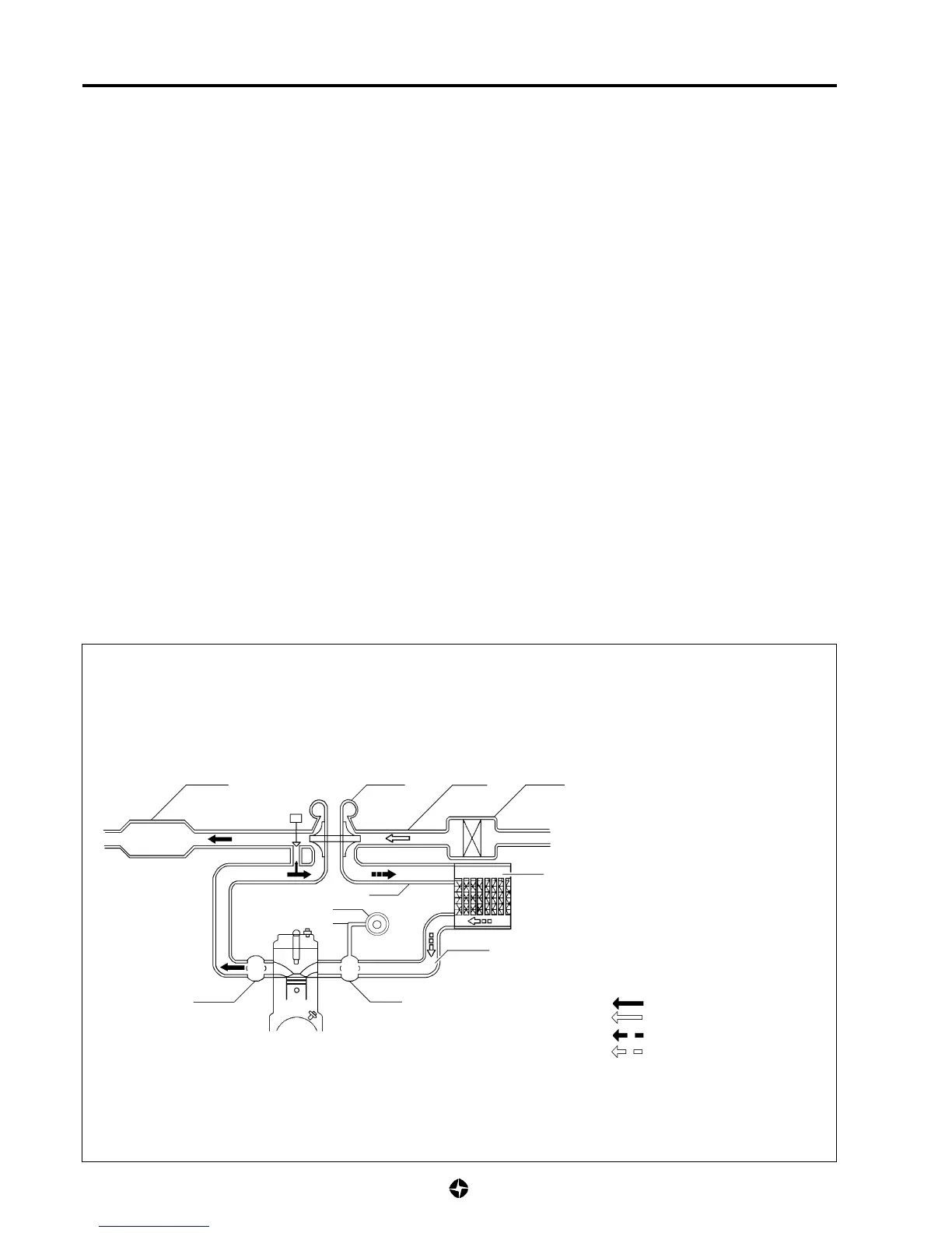
AIR INTAKE SYSTEM DIAGRAM
1. Air filter.
2. Air inlet pipe to turbocharger.
3. Turbocharger.
4. Air outlet pipe from turbocharger to intercooler.
5. Heat interchanger (intercooler).
6. Cold air outlet pipe from intercooler to intake
manifold.
7. Intake manifold.
8. Exhaust manifold.
9. Silencer and exhaust pipe.
10. Pressure tube to LDA.
(mechanical injection engine)
11. LDA device.
(mechanical injection engine).
Exhaust gases
Suction admision air
Compresed admission air (hot)
Compresed admission air (cold)
4
10
11
6
5

 Loading...