2 Installation
2.2 Component description
11
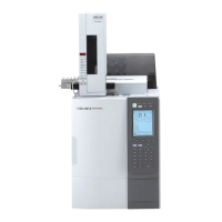
GC-2010 Plus
∗ Only for units with AOC-20i.
NOTE The symbol indicates the functional ground terminal.
CAUTION
Do not touch the connections or terminals when the power is on. This
could damage the circuits.
No. Name Description
1 Power cable Supplies power to the unit.
2 Air Inlet Fan Sends air to the column oven to cool it down.
3 Partition Plate Prevents the air from flowing back into the column oven.
4 Exhaust vent This vents the column oven during cooling.
5 Carrier gas inlet Supplies carrier gas.
6 Detector gas inlet Supplies detector gas.
7 START signal input terminal
Connect an external device if any to this terminal to receive a
start signal.
8 READY signal terminal
Outputs the READY signal to any external device (Such as the
auto injector).
9 START signal output terminal
Connect an external device if any to this terminal to output the
start signal.
10 RS-232C connector
Connect the RS-232C cable (9-pin) to this connector. For I/O of
digital signal.
11 Relay terminal Relay terminal to switch at EVENT91 and 92.
12 AOC communication connector
Connect this connector to the RS-232C terminal in the power
unit of AOC-20 i/s.
13
Detector signal output terminal
(analog)
Outputs the detector signal to analog input of a Chromatopac or
other type of data processing unit. (ch1, ch2)
14 AOC power supply * Connects AOC-20i and AOC-20s (option).
14-1
14-2
14-3
14-4
14-5
14-6
INJECTOR1 connector
INJECTOR2 connector
SAMPLER connector
RS-232C connector
Fiber optic cable connector
Start out/Ready in connector
Connect the auto injector. (in single mode)
Connect the main auto injector in dual mode.
Connect the subordinate auto injector in dual mode.
Connect the autosampler carousel.
Connector for external control
Do not connect RS-232C and fiber optic cables simultaneously.
Inputs the Ready signal to the gas chromatograph and outputs
the start signal from the gas chromatograph.

 Loading...
