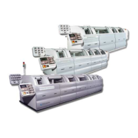
CONVEYOR ENHANCEMENTS
Photocell Adjustments
6-104 Aquastorm™ Series Options Guide Rev. 1
6
Procedure Use the following steps to raise or lower the emitter and reflector:
1. Place product with the lowest components for processing in the path
between the photocell emitter and reflector.
2. Use a 5 mm socket wrench to loosen the bolts securing the photocell emitter
mounting bracket enough to allow slight vertical movement.
3. Slowly lower or raise the emitter until the LED on the photocell emitter does
not illuminate.
4. Secure the mounting hardware on the photocell emitter mounting bracket.
5. Repeat Step 2. through Step 4. for the photocell reflector mounting bracket.
It may be necessary to loosen and move both units simultaneously.
6. Ensure the photocell emitter and reflector remain in the set position.
7. After securing the mounting hardware, verify the green LED still operates by
removing sample product from the photocell path.
8. If the green LED on the photocell emitter does not illumine when product is
removed, repeat the process until the photocell is properly mounted.
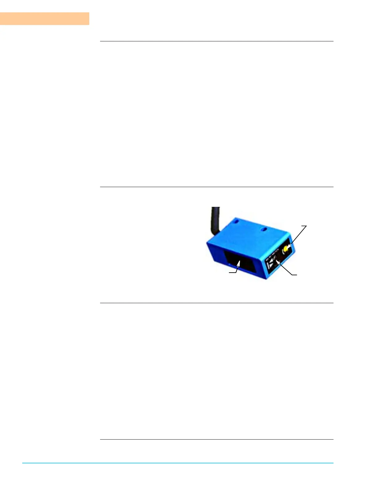
Photograph Figure 6–16 shows a close up view of the photocell sensor unit.
Figure 6–16
Procedure Use the following steps to adjust photocell sensitivity:
1. Ensure system power is On.
2. Remove any objects obstructing the emitter path.
3. Verify photocell alignment.
4. Place product with the lowest components for processing in the path of the
photocell emitter and reflector.
5. Using a small jeweler size flat head screwdriver, turn the sensitivity adjust-
ment screw on the photocell emitter clockwise in ¼ turn increments until the
green LED remains illuminated.
6. To determine the point of sensitivity, turn the sensitivity adjustment screw on
the photocell emitter counterclockwise in ¼ turn increments until the LED
flashes between red and green.
7. To complete the sensitivity adjustment, turn the sensitivity adjustment screw
clockwise ¼ turn.
Photocell Emitter
Sensitivity Adjust
Screw
Green/Red
LED Indicator
 Loading...