SUMP PUMP
Overview
17-330 Aquastorm™ Series Options Guide Rev. 1
17
Section A:
. . . . . . . . . . . . . . . . . . . . . . . . . . . . . . . . . . .
Functional Description
Overview
Introduction At the time of manufacture, Aquastorm™ systems are configured with a single
drain system or a dual drain system. In some customer facilities drain plumbing is
not directly available to an Aquastorm™ system at the installation site. A ¾ HP or
2 HP single sump pump unit can be connected to the single drain system. For
dual drain Aquastorm systems, two (2) sump pumps can be installed.
The 2 HP sump pump is often connected between the split rinse drain and a
closed loop recycling system external to the pump and Aquastorm™ system.
As the Aquastorm™ system operates drain discharge exits the system into the
facility drain plumbing, or into the sump pump. When the sump pump unit
reaches its operating level, the pump activates and pumps the discharge to
remote drain plumbing or to a closed loop treatment system for recycling.
Safety To ensure personal safety and avoid equipment damage observe the following:
ATTENTION
Waste water discharge solutions from Aquastorm™ systems may be regulated by
local, county, state, or federal agencies. Indiscriminate discharge is not
recommended. Refer to the chemical manufacturer MSDS for specific information
and contact a local governing agency for proper permits, discharge requirements,
and pre-treatment conditioning prior to operating the system and the sump pump.
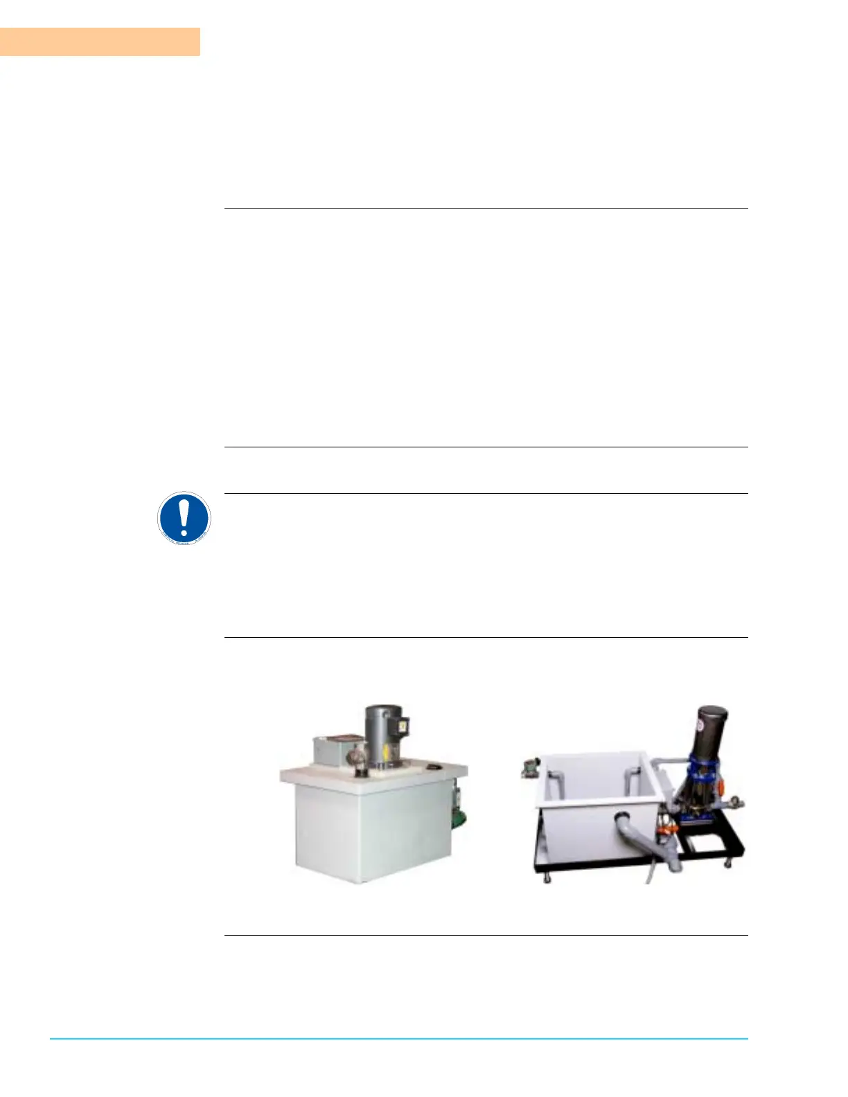
Diagram Figure 17–1 shows the standard ¾ HP sump pump unit on the left and the 2 HP
sump pump unit on the right.
Figure 17–1