RESISTIVITY MONITOR
Calibrate Resistivity Monitor
10-194 Aquastorm™ Series Options Guide Rev. 1
10
Calibrate Resistivity Monitor
Introduction When purchased with a new system, the resistivity meter minimum and
maximum resistivity readings between the meter and the Aquastorm™ control
panel are set at the factory. In the unlikely event calibration need reconfiguration,
the following information covers the steps to recalibrate and verify the resistivity
meter to control panel readings.
Safety To ensure personal safety and avoid equipment damage observe the following:
Electrical Hazard
Qualified electrical maintenance staff should perform the following meter
adjustments.
Tools Use the following tools for resistivity monitor configuration:
• AMP Meter
• Standard screwdriver
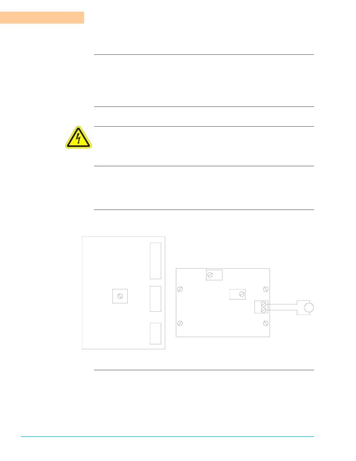
Diagram Figure 10–6 shows the control board and transmitter board layout diagrams and
indicate the AMP meter connection location.
Figure 10–6
TB3
TB2
TB1
R31
Control Board
Transmitter Board
R20
R23
1
2
mA
+
+
–
–
TB1
 Loading...