. . . . .
RESISTIVITY MONITOR
Overview
2-9317-600-00-0 Aquastorm™ Series Options Guide 10-197
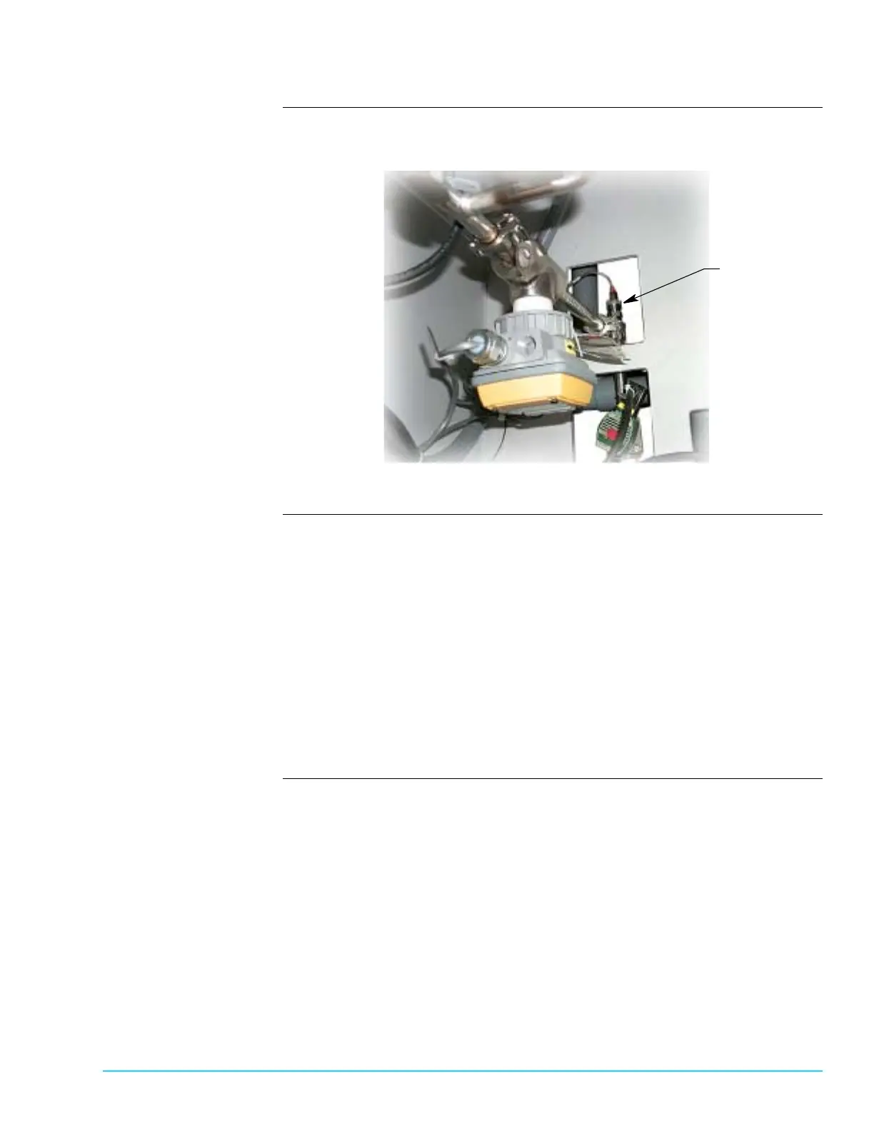
Photograph Figure 10–7 shows the rear final rinse bulkhead floor and identifies the resistivity
probe location.
Figure 10–7
Procedure Perform the following routine maintenance:
1. Turn Aquastorm™ system Off.
2. Remove system rear panels.
3. Use channel lock pliers to loosen the reisitivity probe from the lower final
rinse plumbing.
4. Check the probe for lime deposits, and clean if necessary.
5. Use channel lock pliers to replace the reisitivity probe into the lower final rinse
plumbing.
6. Replace system rear panels.
7. Turn Aquastorm™ system On and resume system operation. For detailed infor-
mation refer to the Aquastorm 200™ Programming and Operations Guide.
Resistivity Probe
 Loading...