HURRICANE JETS™ AND PUMPS
Theory of Operation
11-208 Aquastorm™ Series Options Guide Rev. 1
11
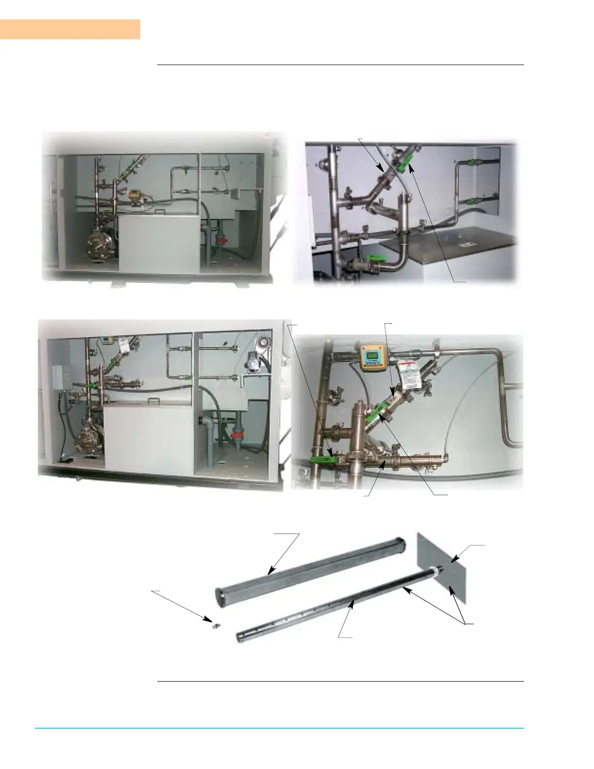
Photographs Figure 11–6 shows the rear prewash and wash section and close-up of a single
Hurricane Jet™ configuration. Figure 11–7 shows the rear prewash and wash
section and close-up of a dual Hurricane Jet™ configuration. Figure 11–8 shows a
Hurricane Jet™ nozzle assembly drawing.
Figure 11–6
Figure 11–7
Figure 11–8
Hurricane Jet™ Plumbing Connections
On/Off Valve
in On Position
Upper Hurricane Jet™ Plumbing
Upper On/Off Valv
Lower Hurricane Jet™ Plumbing
Lower On/Off Valve
in On Position
in On Position
Hurricane Jet™ Nozzle
Cap Screw
Internal Spray Bar
Mounting
Bracket
Hurricane
Manifold
 Loading...