. . . . .
NATURAL GAS HEATING
Plumbing Connections
2-9317-600-00-0 Aquastorm™ Series Options Guide 12-233
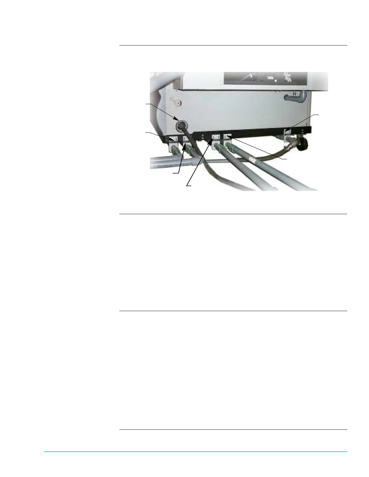
Photograph Figure 12–3 shows the exit end of an Aquastorm 200™ system connected to two
(2) natural gas water heaters.
Figure 12–3
Procedure Connect all Aquastorm™ wash section natural gas water heaters as follows:
1. Connect the facility natural gas line to the natural gas water heater.
2. Connect the facility water source to the standard Aquastorm™ inlet plumbing.
3. Connect the water heater exit plumbing line to the wash input plumbing line.
4. Connect the wash exit plumbing line back into the water heater input line.
5. Ensure all fittings are snug and no water or gas leaks are present.
6. Turn Aquastorm™ system On and begin filling wash tank.
7. When tank is full, turn facility natural gas On to begin heating water in the
water heater.
Procedure Connect the Aquastorm 200™ rinse section natural gas water heater as follows:
1. Connect the facility natural gas line to the second natural gas water heater.
2. Connect the second water heater exit line plumbing to the rinse input plumb-
ing line.
3. Connect the second water heater exit plumbing back into the water heater
input line.
4. Ensure all fitting are snug and no water or gas leaks are present.
5. Turn Aquastorm™ system On and begin filling rinse tank.
6. When tank is full, turn facility natural gas On to begin heating water in the
water heater.
7. Begin system operation. For detailed information refer to the Aquastorm 200™
Programming and Operation Manual.
Wash Water
Input Connection
Wash Water
Outlet Connection
Rinse Water
Input Connection
Rinse Water
Outlet Connection
Facility
Power
Weir Drain
System
 Loading...