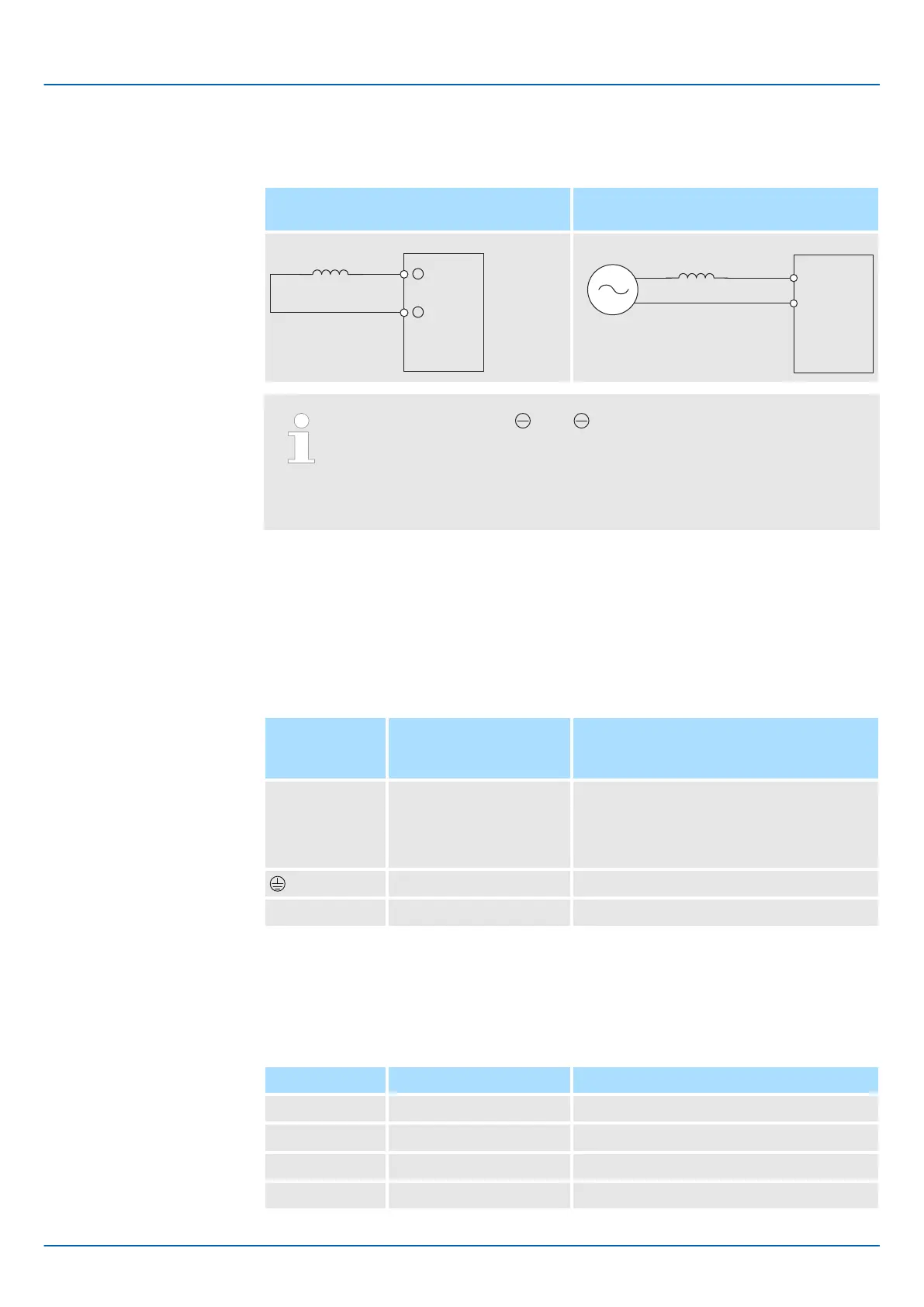
Refer to the following figures to connect reactors.
SERVOPACK with Three-Phase, 200-
VAC Power Supply Input
SERVOPACK with Single-Phase, 100-
VAC Power Supply Input
SERVOPACK
L1
L2
AC Reactor
Power supply
– Connection terminals 1 and 2 for a DC Reactor are connected
when the SERVOPACK is shipped. Remove the lead wire and con-
nect a DC Reactor.
– Reactors are optional products. (Purchase them separately.)
– You cannot connect a DC Reactor to a SERVOPACK with a single-
phase, 100-VAC power supply input.
5.5 Wiring Servomotors
5.5.1 Terminal Symbols and Terminal Names
The SERVOPACK terminals or connectors that are required to connect the SERVOPACK
to a Servomotor are given below.
Terminal/
Connector
Symbols
Terminal/Connector
Name
Remarks
U, V, and W Servomotor terminals Refer to the following section for the wiring
procedure.
Ä
Chap. 5.4.3 ‘Wiring Procedure for Main
Circuit Connector’ page 96
Ground terminal –
CN2 Encoder connector –
5.5.2 Pin Arrangement of Encoder Connector (CN2)
n When Using a Rotary Servomotor
Pin No. Signal Function
1 PG5V Encoder power supply +5 V
2 PG0V Encoder power supply 0 V
3 BAT (+)* Battery for absolute encoder (+)
4 BAT (-)* Battery for absolute encoder (-)
Sigma-7 Series SERVOPACKs
Wiring and Connecting SERVOPACKs
Wiring Servomotors > Pin Arrangement of Encoder Connector (CN2)
| | PROFINET Communications - SIEP YEUOC7P 02A Revision 0 | en | 107

 Loading...


