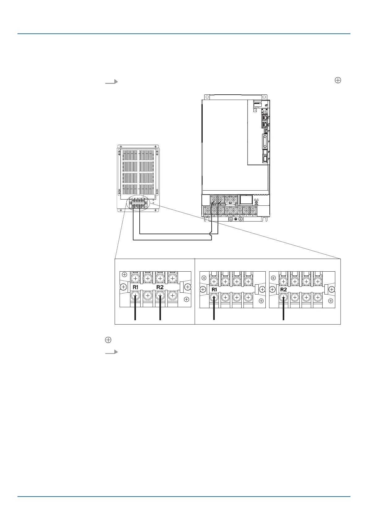
1.
Connect the R1 and R2 terminals on the Regenerative Resistor Unit to the B1/
and B2 terminals on the SERVOPACK.
Fig. 62: Connecting the R1 and R2 terminals on the Regenerative Resistor Unit to the B1/
and B2 terminals on the SERVOPACK
2. Set Pn600 (Regenerative Resistor Capacity) and Pn603 (Regenerative Resistance)
as required.
n When using the Yaskawa-recommended Regenerative Resistor Unit, use the
default settings for Pn600 and Pn603.
n If you use any other external regenerative resistor, set Pn600 and Pn603
according to the specifications of the regenerative resistor.
Refer to the following section for details on the settings.
Ä
Chap. 6.18 ‘Setting the Regenerative Resistor Capacity’ page 194
5.4.7 Wiring Reactors for Harmonic Suppression
You can connect a reactor for harmonic suppression to the SERVOPACK when power
supply harmonic suppression is required. Refer to the following manual for details on
reactors for harmonic suppression.
& Σ-7-Series Peripheral Device Selection Manual (Manual No.: SIEP S800001 32)
SERVOPACK Models
SGD7S-470A, -550A,
-590A, and -780A
Sigma-7 Series SERVOPACKs
Wiring and Connecting SERVOPACKs
Wiring the Power Supply to the SERVOPACK > Wiring Reactors for Harmonic Suppression
| | PROFINET Communications - SIEP YEUOC7P 02A Revision 0 | en | 106

 Loading...


