5.7 Connecting Safety Function Signals
5.7.1 Overview
This section describes the wiring required to use a safety function.
Refer to the following chapter for details on the safety function.
Ä
Chap. 12 ‘Safety Functions’ page 466
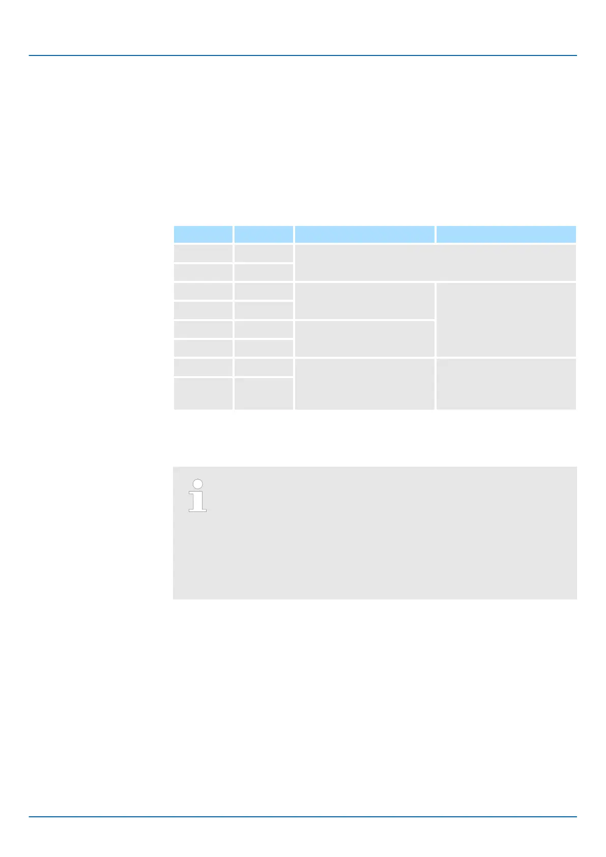
5.7.2 Pin Arrangement of Safety Function Signals (CN8)
Pin No. Signal Name Function
1 − - (Do not use these pins because they are connected to
internal circuits.)
2 −
3 /HWBB1- Hard Wire Base Block Input 1 For a hard wire base block
input. The base block (motor
power turned OFF) is in
effect when the signal is OFF.
4 /HWBB1+
5 /HWBB2- Hard Wire Base Block Input 2
6 /HWBB2+
7 EDM1- External Device Monitor
Output
Turns ON when the /HWBB1
and the / HWBB2 signals are
input and the SERVOPACK
enters a base block state.
8 EDM1+
5.7.3 I/O Circuits
For safety function signal connections, the input signal is the 0-V
common and the output signal is a source output. This is opposite to
other signals described in this manual.
To avoid confusion, the ON and OFF status of signals for the safety func-
tion are defined as follows:
– ON: The state in which the relay contacts are closed or the transistor
is ON and current flows into the signal line.
– OFF: The state in which the relay contacts are open or the transistor
is OFF and no current flows into the signal line.
Use a 0-V common to connect the safety function signals. You must connect redundant
input signals.
Safety Input Circuits
Sigma-7 Series SERVOPACKs
Wiring and Connecting SERVOPACKs
Connecting Safety Function Signals > I/O Circuits
| | PROFINET Communications - SIEP YEUOC7P 02A Revision 0 | en | 124

 Loading...


