5. If the feedback pulse counter counts up, set a phase-A lead as a phase sequence
of U, V, and W (Pn080 = n.0).
If the feedback pulse counter counts down, set a phase-B lead as a phase
sequence of U, V, and W (Pn080 = n.1).
6. Turn the power supply to the SERVOPACK OFF and ON again.
7.
If necessary, return Pn000 = n.X (Direction Selection) to its original setting.
ð
This concludes the procedure to set the phase sequence of the Linear Servo-
motor.
In this example, assume that a linear encoder with a scale pitch of 20 μm and a resolu-
tion of 256 is used. If you manually move the Moving Coil 1 cm in the count-up direction
of the linear encoder, the number of feedback pulses would be as follows: 1 cm/(20 μm/
256) = 128,000 pulses
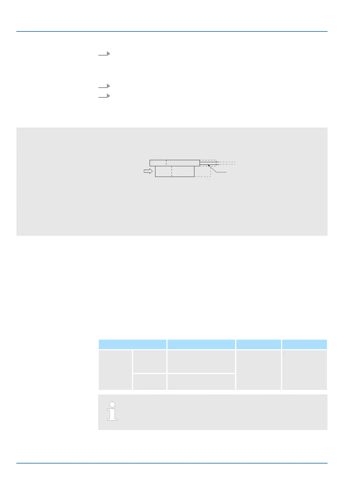
Cable for Linear Servomotor
Moving Coil
Fig. 109: Selecting the Phase Sequence for a Linear Servomotor
If there are 128,000 pulses on the feedback pulse counter after you manually move the
Moving Coil in the direction of the cable, you have completed the confirmation.
Note: The actual monitor display will be offset by the error in the travel distance. There is
no problem as long as the above value is close to the calculated value.
Example
6.9 Polarity Sensor Setting
The polarity sensor detects the polarity of the Servomotor. You must set a parameter to
specify whether the Linear Servomotor that is connected to the SERVOPACK has a
polarity sensor. Specify whether there is a polarity sensor in Pn080 = n.X (Polarity
Sensor Selection).
If the Linear Servomotor has a polarity sensor, set Pn080 to n.0 (Use polarity
sensor) (default setting).
If the Linear Servomotor does not have a polarity sensor, set Pn080 to n.1 (Do not
use polarity sensor). Turn the power supply OFF and ON again to enable the new setting.
Parameter Meaning When Enabled Classification
Pn080
n.0
(default
setting)
Use polarity sensor. After restart Setup
n.1
Do not use polarity
sensor.
If you set Pn080 to n.
0 (Use polarity sensor) and the Linear Servo-
motor that is connected to the SERVOPACK does not have a polarity
sensor, an A.C21 alarm (Polarity Sensor Error) will occur when you turn
the power supply OFF and ON again.
Sigma-7 Series SERVOPACKs
Basic Functions That Require Setting before Operation
Polarity Sensor Setting
| | PROFINET Communications - SIEP YEUOC7P 02A Revision 0 | en | 156

 Loading...


