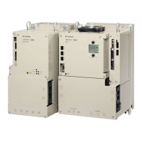
2.5 Part Names
(on side of
SERVOPACK)
Main circuit
terminals
Motor
terminals
With Front Cover Open
L2L1 L3
L1C
L2C
B1/
B2 B3
1 2
U V W
12
13
14
18
19
20
15
16
17
21
22
23
24
11
25
12
26
Fig. 9: Part Names SGD7S-1R6A
No. Name Description Reference
1 Front Cover − −
2 Input Voltage − −
3 Nameplate Indicates the SERVOPACK model and ratings.
Ä
Chap. 2.4 ‘Interpreting
the Nameplate’ page 43
4 Model The model of the SERVOPACK.
Ä
Chap. 2.6 ‘Model
Designations’ page 46
5 QR Code The QR code that is used by the Mechatro-
Cloud service.
−
6 CHARGE Lit while the main circuit power is being sup-
plied.
Note: Even if you turn OFF the main circuit
power supply, this indicator will be lit as long
as the internal capacitor remains charged. Do
not touch the main circuit or motor terminals
while this indicator is lit. Doing so may result in
electric shock.
–
7 Main Circuit Terminals The terminals depend on the main circuit
power supply input specifications of the SER-
VOPACK.
Ä
Chap. 5.4.2 ‘Terminal
Symbols and Terminal
Names’ page 92
8 Servomotor Terminals (U, V, and
W)
The connection terminals for the Servomotor
Main Circuit Cable (power line).
Ä
Chap. 5.5.1 ‘Terminal
Symbols and Terminal
Names’ page 107
9
Ground Terminal ( )
The ground terminals to prevent electric
shock. Always connect this terminal.
–
10 Serial Communications Connector
(CN502)
Connects to the Digital Operator. However, a
Communications Unit (JUSP-JC001-1) is
required to connect a Digital Operator.
Ä
Chap. 5.9.1 ‘Serial
Communications Con-
nector (CN502)’
page 128
Sigma-7 Series SERVOPACKs
Basic Information on SERVOPACKs
Part Names
| | PROFINET Communications - SIEP YEUOC7P 02A Revision 0 | en | 44

 Loading...


