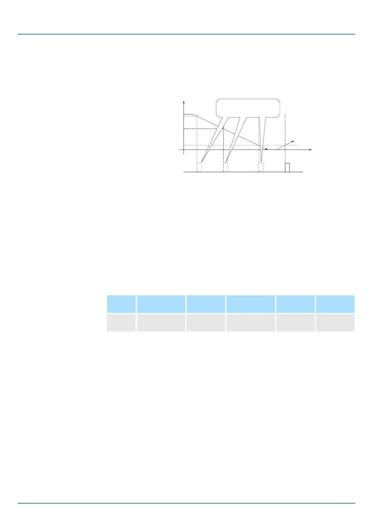
The encoder’s phase-C pulse is not output when the origin detection position is passed
for the first time in the reverse direction after the power supply is turned ON.
However, after the origin detection position is passed in the forward direction and the
encoder’s phase-C pulse it output, it will then also be output when the origin detection
point is passed in the reverse direction.
Encoder count-up
direction
Origin 1 detection
position
Origin 2 detection
position
Origin 3 detection
position
Power ON
Phase-C pulse
output
Origin 1
Origin 2 Origin 3 Origin 3
Time
The phase-C pulse is not
output.
Fig. 161: Magnescale Linear Incremental Encoder - When using a Linear encoder with
multiple origins and first passing the Origin position in the reverse direction
7.6.3 Setting for the Encoder Divided Pulse Output
This section describes the setting for the encoder divided pulse output for a Rotary Ser-
vomotor or Linear Servomotor.
If you will use a Rotary Servomotor, set the number of encoder output pulses (Pn212).
Number of Encoder Output Pulses
Setting Range Setting
Unit
Default Setting When Ena-
bled
Classifica-
tion
Pn212 16 to
1,073,741,824
1 P/Rev 2,048 After restart Setup
(applies to Speed Control, Position Control and Torque Control)
The number of pulses from the encoder per rotation are processed inside the SERVO-
PACK, divided by the setting of Pn212, and then output.
Set the number of encoder divided output pulses according to the system specifications
of the machine or host controller.
The setting of the number of encoder output pulses is limited by the resolution of the
encoder.
Encoder Divided Pulse
Output When Using a
Rotary Servomotor
Sigma-7 Series SERVOPACKs
Application Functions
Encoder Divided Pulse Output > Setting for the Encoder Divided Pulse Output
| | PROFINET Communications - SIEP YEUOC7P 02A Revision 0 | en | 218

 Loading...


