2.
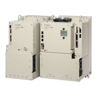
Connect the External Regenerative Resistor between the B1/ and B2 terminals.
Fig. 61: Connecting the External Regenerative Resistor between the B1/ and B2 termi-
nals
3. Set Pn600 (Regenerative Resistor Capacity) and Pn603 (Regenerative Resist-
ance).
Refer to the following section for details on the settings.
Ä
Chap. 6.18 ‘Setting the Regenerative Resistor Capacity’ page 194
Sigma-7 Series SERVOPACKs
Wiring and Connecting SERVOPACKs
Wiring the Power Supply to the SERVOPACK > Wiring Regenerative Resistors
| | PROFINET Communications - SIEP YEUOC7P 02A Revision 0 | en | 105

 Loading...


