0 V
Emergency stop
5 VDC to 30 VDC
SERVOPACK
Photocoupler
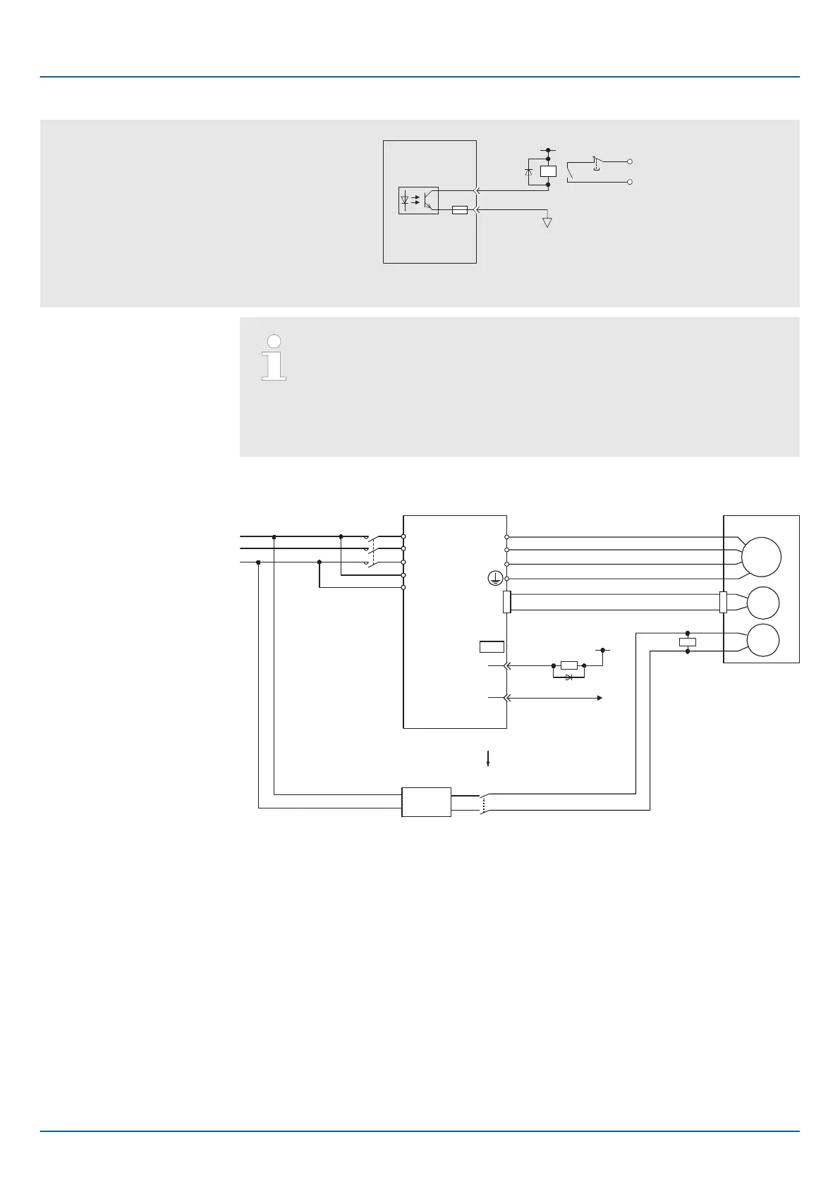
Fig. 77: Relay Circuit Example
Relay Circuit Example
– You can change the output signal allocation of the /BK signal. Refer
to the following section for details.
Ä
Chap. 6.12.3 ‘/BK (Brake) Signal’ page 169
– If you use a 24-V brake, install a separate power supply for the 24-
VDC power supply from other power supplies, such as the one for the
I/O signals of the CN1 connector. If the power supply is shared, the
I/O signals may malfunction.
Servomotor with
Holding Brake
SERVOPACK
Surge Absorber
Power supply
BK-RY: Brake control relay
1D: Flywheel diode
M
BK
ENC
U
V
W
CN2
AC DC
BK-RY
BK-RY
+24 V
L1
L2
L3
L1C
L2C
(/BK+)
(/BK-)
CN1
Brake power supply
DC side
1D
0 V
*
Fig. 78: Wiring example for SERVOPACKs without built-in Servomotor brake control
* Install the Surge Absorber near the brake terminals on the Servomotor.
Sigma-7 Series SERVOPACKs
Wiring and Connecting SERVOPACKs
Wiring Servomotors > Wiring the SERVOPACK to the Holding Brake
| | PROFINET Communications - SIEP YEUOC7P 02A Revision 0 | en | 115

 Loading...


