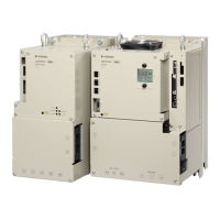
Regenerative Resistor Capacity
Setting
Range
Setting Unit Default Set-
ting
When Ena-
bled
Classifica-
tion
Pn600 0 to SERVO-
PACK’s
maximum
applicable
motor
capacity
10 W 0 Immediately Setup
(applies to Speed Control, Position Control and Torque Control)
Regenerative Resistor Resistance
Setting
Range
Setting Unit Default Set-
ting
When Ena-
bled
Classifica-
tion
Pn603 0 to 65,535 10 mΩ 0 Immediately Setup
(applies to Speed Control, Position Control and Torque Control)
Set the Regenerative Resistor capacity to a value that is consistent with the allowable
capacity of the External Regenerative Resistor. The setting depends on the cooling condi-
tions of the External Regenerative Resistor.
n For self-cooling (natural convection cooling): Set the parameter to a maximum 20% of
the capacity (W) of the actually installed Regenerative Resistor.
n For forced-air cooling: Set the parameter to a maximum 50% of the capacity (W) of
the actually installed Regenerative Resistor.
For a self-cooling 100-W External Regenerative Resistor, set Pn600 to 2 (×10 W) (100
W × 20% = 20 W).
Example
– An A.320 alarm will be displayed if the setting is not suitable.
– The default setting of 0 specifies that the SERVOPACK’s built-in
regenerative resistor or Yaskawa’s Regenerative Resistor Unit is
being used.
– When an External Regenerative Resistor is used at the normal rated
load ratio, the resistor temperature increases to between 200°C and
300°C. Always apply derating. Consult the manufacturer for the resis-
tor’s load characteristics.
– For safety, use an External Regenerative Resistor with a thermos-
witch.
Sigma-7 Series SERVOPACKs
Basic Functions That Require Setting before Operation
Setting the Regenerative Resistor Capacity
| | PROFINET Communications - SIEP YEUOC7P 02A Revision 0 | en | 195

 Loading...


