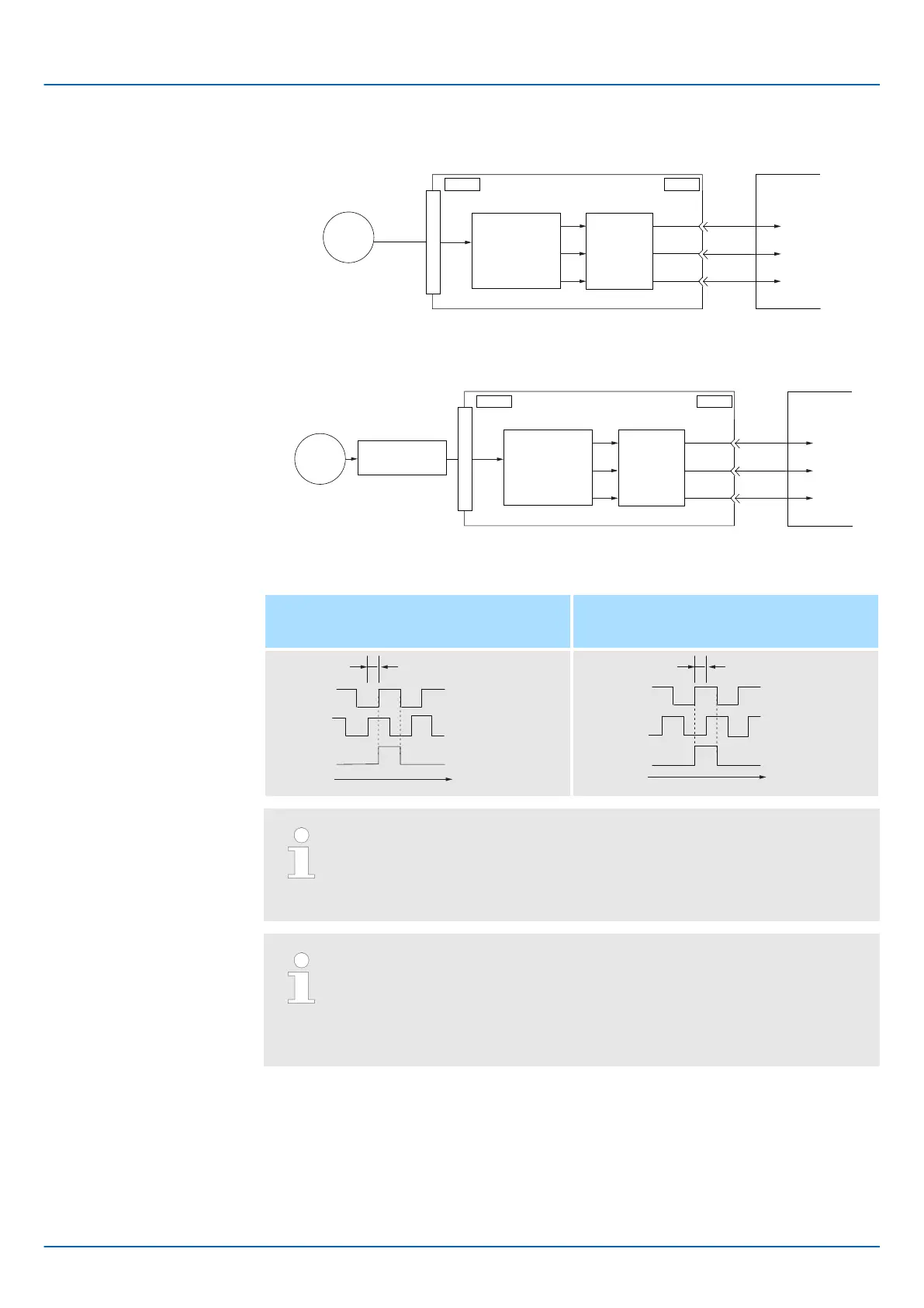
n Rotary Servomotor
ENC
CN1CN2
PAO
PBO
PCO
(Pn212)
SERVOPACK
Host controller
Serial
data
Conversion of
serial data to
pulses
Dividing
circuit
Fig. 153: Encoder Signal Output - Rotary Servomotor
n Linear Servomotors
ENC
CN1
CN2
PAO
PBO
PCO
(Pn281)
Linear
encoder
Serial data
Serial
Converter Unit
SERVOPACK
Conversion of
serial data to
pulses
Dividing
circuit
Host controller
Fig. 154: Encoder Signal Output - Linear Servomotor
Forward rotation or movement
(phase B leads by 90°)
Reverse rotation or movement
(phase A leads by 90°)
90°
t
Phase A
Phase B
Phase C
90°
t
Phase C
Phase B
Phase A
The pulse width of the origin within one encoder rotation depends on the
setting of number of encoder output pulses (Pn212) or the encoder output
resolution (Pn281). It is the same as the width of phase A. Even for
reverse operation (Pn000 = n.
1), the output phase form is the same
as shown above.
If you use the SERVOPACK’s phase-C pulse output for an origin return,
rotate the Servomotor two or more rotations before you start an origin
return. If the Servomotor cannot be rotated two or more times, perform an
origin return operation at a motor speed of 600 min
-1
or lower. If the motor
speed is higher than 600 min
-1
, the phase-C pulse may not be output cor-
rectly.
The following precautions apply to the encoder output pulses when an external linear
encoder is used.
Relation between Renishaw PLC Incremental Linear Encoders and Encoder Output
Pulse Signal from the SERVOPACK when using a RGS20 Scale and RGH22B
Sensor Head
Output Phase Forms
Linear Encoder Applica-
tion Precautions
Sigma-7 Series SERVOPACKs
Application Functions
Encoder Divided Pulse Output > Encoder Divided Pulse Output Signals
| | PROFINET Communications - SIEP YEUOC7P 02A Revision 0 | en | 214

 Loading...


