Parameter Position
Control
Gain
Switching
Condition A
For Control
Methods Other
Than Position
Control (No
Switching)
When Ena-
bled
Classifica-
tion
n.2
/NEAR
(Near) signal
ON
Gain settings 1
used.
n.3
/NEAR
(Near) signal
OFF
Gain settings 2
used.
n.4
Position ref-
erence filter
output is 0
and position
reference
input is OFF.
Gain settings 1
used.
n.5
Position ref-
erence input
is ON.
Gain settings 2
used.
Pn104
Pn105
Pn106
Pn122
Pn412
Pn100
Pn101
Pn102
Pn121
Pn401
Automatic Switching Pattern 1 (Pn139 = n.ooo2)
Gain settings 1:
Condition A
satisfied
Condition A
not satisfied
Gain settings 2:
Gain Switching Time 1: Pn131
Switching Waiting Time 1: Pn135
Switching Waiting Time 2: Pn136
Gain Switching Time 2: Pn132
Fig. 289: Automatic Gain Switching
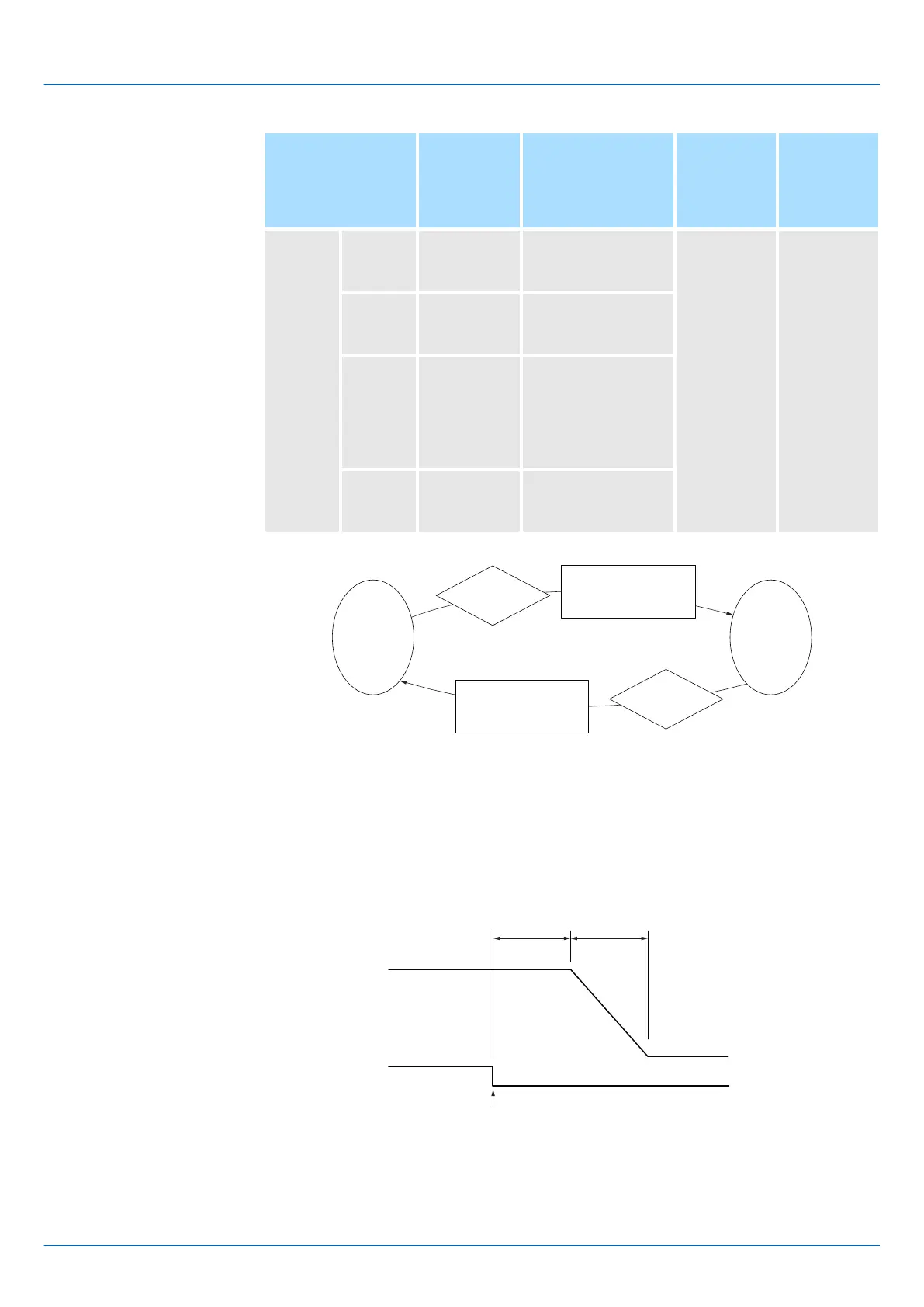
n Relationship between the Waiting Times and Switching Times for Gain Switching
In this example, an ON /COIN (Positioning Completion) signal is set as condition A for
automatic gain switching. The position loop gain is changed from the value in Pn102
(Position Loop Gain) to the value in Pn106 (Second Position Loop Gain). When the /
COIN signal turns ON, the switching operation begins after the waiting time (Pn135). The
switching operation changes the position loop gain linearly from the gain set in Pn102 to
the gain set in Pn106 over the switching time (Pn131).
Pn102
Position Loop Gain
Pn106
/COIN
Waiting
time: Pn135
Switching
time: Pn131
Second
Position Loop Gain
Switching condition A satisfied.
Fig. 290: Relationship between the Waiting Times and Switching Times for Gain
Switching
Sigma-7 Series SERVOPACKs
Tuning
Additional Adjustment Functions > Gain Switching
| | PROFINET Communications - SIEP YEUOC7P 02A Revision 0 | en | 391

 Loading...


