SUPPLEMENTAL INFLATABLE RESTRAINTS (SIR) 8B–21
DAEWOO M-150 BL2
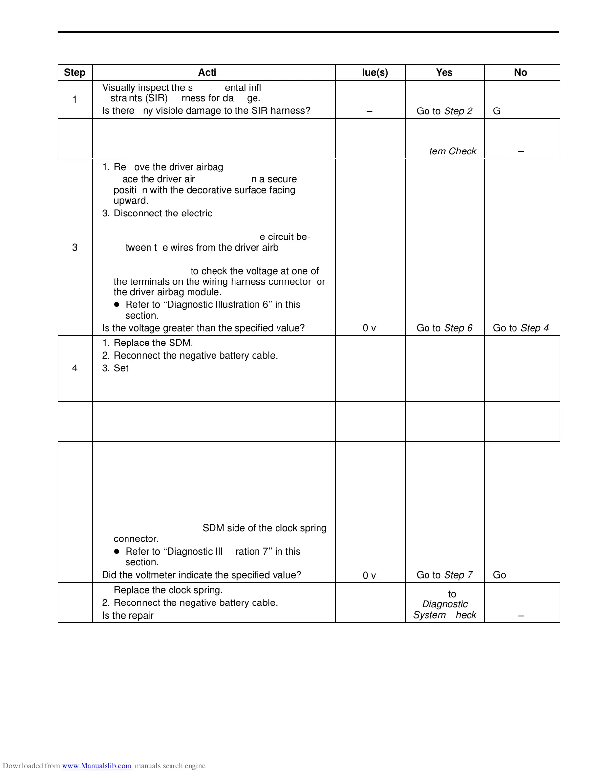
DTC 04 – Driver Firing Circuit, Short To Battery Voltage
Step
ÁÁÁÁÁÁÁÁÁÁÁÁÁÁÁÁÁ
ÁÁÁÁÁÁÁÁÁÁÁÁÁÁÁÁÁ
Action
Value(s)
Yes
No
ÁÁ
1
ÁÁÁÁÁÁÁÁÁÁÁÁÁÁÁ
Visually inspect the supplemental inflatable
restraints (SIR) harness for damage.
Is there any visible damage to the SIR harness?
ÁÁÁ
–
ÁÁÁÁÁ
Go to Step 2
ÁÁÁÁ
Go to Step 3
ÁÁ
ÁÁ
2
ÁÁÁÁÁÁÁÁÁÁÁÁÁÁÁ
ÁÁÁÁÁÁÁÁÁÁÁÁÁÁÁ
1. Replace the SIR wiring harness.
2. Reconnect the negative battery cable.
Is your repair complete?
ÁÁÁ
ÁÁÁ
–
ÁÁÁÁÁ
ÁÁÁÁÁ
Go to
Diagnostic
System Check
ÁÁÁÁ
ÁÁÁÁ
–
ÁÁ
ÁÁ
ÁÁ
ÁÁ
ÁÁ
ÁÁ
ÁÁ
ÁÁ
ÁÁ
ÁÁ
ÁÁ
3
ÁÁÁÁÁÁÁÁÁÁÁÁÁÁÁ
ÁÁÁÁÁÁÁÁÁÁÁÁÁÁÁ
ÁÁÁÁÁÁÁÁÁÁÁÁÁÁÁ
ÁÁÁÁÁÁÁÁÁÁÁÁÁÁÁ
ÁÁÁÁÁÁÁÁÁÁÁÁÁÁÁ
ÁÁÁÁÁÁÁÁÁÁÁÁÁÁÁ
ÁÁÁÁÁÁÁÁÁÁÁÁÁÁÁ
ÁÁÁÁÁÁÁÁÁÁÁÁÁÁÁ
ÁÁÁÁÁÁÁÁÁÁÁÁÁÁÁ
ÁÁÁÁÁÁÁÁÁÁÁÁÁÁÁ
ÁÁÁÁÁÁÁÁÁÁÁÁÁÁÁ
1. Remove the driver airbag module.
2. Place the driver airbag module in a secure
position with the decorative surface facing
upward.
3. Disconnect the electrical connector at the SDM.
D The shorting bar at the disconnected SDM
connector will create a complete circuit be-
tween the wires from the driver airbag
module.
4. Use a multimeter to check the voltage at one of
the terminals on the wiring harness connector for
the driver airbag module.
D Refer to ‘‘Diagnostic Illustration 6’’ in this
section.
Is the voltage greater than the specified value?
ÁÁÁ
ÁÁÁ
ÁÁÁ
ÁÁÁ
ÁÁÁ
ÁÁÁ
ÁÁÁ
ÁÁÁ
ÁÁÁ
ÁÁÁ
ÁÁÁ
0 v
ÁÁÁÁÁ
ÁÁÁÁÁ
ÁÁÁÁÁ
ÁÁÁÁÁ
ÁÁÁÁÁ
ÁÁÁÁÁ
ÁÁÁÁÁ
ÁÁÁÁÁ
ÁÁÁÁÁ
ÁÁÁÁÁ
ÁÁÁÁÁ
Go to Step 6
ÁÁÁÁ
ÁÁÁÁ
ÁÁÁÁ
ÁÁÁÁ
ÁÁÁÁ
ÁÁÁÁ
ÁÁÁÁ
ÁÁÁÁ
ÁÁÁÁ
ÁÁÁÁ
ÁÁÁÁ
Go to Step 4
ÁÁ
ÁÁ
ÁÁ
4
ÁÁÁÁÁÁÁÁÁÁÁÁÁÁÁ
ÁÁÁÁÁÁÁÁÁÁÁÁÁÁÁ
ÁÁÁÁÁÁÁÁÁÁÁÁÁÁÁ
1. Replace the SDM.
2. Reconnect the negative battery cable.
3. Set the scan tool for CODE ERASE.
4. Do the diagnostic system check.
Does the code 04 still show as a current fault?
ÁÁÁ
ÁÁÁ
ÁÁÁ
–
ÁÁÁÁÁ
ÁÁÁÁÁ
ÁÁÁÁÁ
Go to Step 5
ÁÁÁÁ
ÁÁÁÁ
ÁÁÁÁ
System OK
ÁÁ
ÁÁ
5
ÁÁÁÁÁÁÁÁÁÁÁÁÁÁÁ
ÁÁÁÁÁÁÁÁÁÁÁÁÁÁÁ
1. Replace the driver airbag module.
2. Reconnect the negative battery cable.
Is the repair complete?
ÁÁÁ
ÁÁÁ
–
ÁÁÁÁÁ
ÁÁÁÁÁ
Go to
Diagnostic
System Check
ÁÁÁÁ
ÁÁÁÁ
–
ÁÁ
ÁÁ
ÁÁ
ÁÁ
ÁÁ
ÁÁ
ÁÁ
ÁÁ
6
ÁÁÁÁÁÁÁÁÁÁÁÁÁÁÁ
ÁÁÁÁÁÁÁÁÁÁÁÁÁÁÁ
ÁÁÁÁÁÁÁÁÁÁÁÁÁÁÁ
ÁÁÁÁÁÁÁÁÁÁÁÁÁÁÁ
ÁÁÁÁÁÁÁÁÁÁÁÁÁÁÁ
ÁÁÁÁÁÁÁÁÁÁÁÁÁÁÁ
ÁÁÁÁÁÁÁÁÁÁÁÁÁÁÁ
ÁÁÁÁÁÁÁÁÁÁÁÁÁÁÁ
1. Disconnect the clock spring wiring harness at the
lower steering column.
D The shorting bar at the disconnected SDM
connector will create a complete circuit be-
tween the wires from the clock spring
connector.
2. Using a multimeter, check the voltage at one of
the terminals on the SDM side of the clock spring
connector.
D Refer to ‘‘Diagnostic Illustration 7’’ in this
section.
Did the voltmeter indicate the specified value?
ÁÁÁ
ÁÁÁ
ÁÁÁ
ÁÁÁ
ÁÁÁ
ÁÁÁ
ÁÁÁ
ÁÁÁ
0 v
ÁÁÁÁÁ
ÁÁÁÁÁ
ÁÁÁÁÁ
ÁÁÁÁÁ
ÁÁÁÁÁ
ÁÁÁÁÁ
ÁÁÁÁÁ
ÁÁÁÁÁ
Go to Step 7
ÁÁÁÁ
ÁÁÁÁ
ÁÁÁÁ
ÁÁÁÁ
ÁÁÁÁ
ÁÁÁÁ
ÁÁÁÁ
ÁÁÁÁ
Go to Step 2
ÁÁ
ÁÁ
7
ÁÁÁÁÁÁÁÁÁÁÁÁÁÁÁ
ÁÁÁÁÁÁÁÁÁÁÁÁÁÁÁ
1. Replace the clock spring.
2. Reconnect the negative battery cable.
Is the repair complete?
ÁÁÁ
ÁÁÁ
–
ÁÁÁÁÁ
ÁÁÁÁÁ
Go to
Diagnostic
System Check
ÁÁÁÁ
ÁÁÁÁ
–