SUPPLEMENTAL INFLATABLE RESTRAINTS (SIR) 8B–63
DAEWOO M-150 BL2
DIAGNOSTIC TROUBLE CODE (DTC) 31
SDM INTERNAL FAULT
Circuit Description
When the ignition switch is turned ON, the sensing and
diagnostic module (SDM) will perform tests to diagnose
malfunctions within itself.
DTC 31 Will Set When
D The SDM does not pass the internal tests.
Test Description
Caution: Before testing, disconnect the negative
battery cable. Wait 1 minute for the SDM capacitor
to discharge. The capacitor supplies reserve power
to deploy the airbags, even if the battery is discon-
nected. Unintentional deployment of the airbags
can cause injury.
DTC 31 – SDM Internal Fault
Step
ÁÁÁÁÁÁÁÁÁÁÁÁÁÁÁÁÁ
ÁÁÁÁÁÁÁÁÁÁÁÁÁÁÁÁÁ
Action
Value(s)
Yes
No
ÁÁ
ÁÁ
1
ÁÁÁÁÁÁÁÁÁÁÁÁÁÁÁ
ÁÁÁÁÁÁÁÁÁÁÁÁÁÁÁ
1. Disconnect the negative battery cable.
2. Replace the SDM.
Is the repair complete?
ÁÁÁ
ÁÁÁ
–
ÁÁÁÁÁ
ÁÁÁÁÁ
Go to
Diagnostic
System Check
ÁÁÁÁ
ÁÁÁÁ
–
DIAGNOSTIC TROUBLE CODE (DTC) 32
SDM CRASH RECORDED
Circuit Description
When the ignition switch is turned ON, the sensing and
diagnostic module (SDM) will perform tests to diagnose
any malfunctions within itself.
DTC 32 Will Set When
D The SDM has previously detected a crash.
Test Description
Caution: Before testing, disconnect the negative
battery cable. Wait 1 minute for the SDM capacitor
to discharge. The capacitor supplies reserve power
to deploy the airbags, even if the battery is discon-
nected. Unintentional deployment of the airbags
can cause injury.
DTC 32 – SDM Crash Recorded
Step
ÁÁÁÁÁÁÁÁÁÁÁÁÁÁÁÁÁ
ÁÁÁÁÁÁÁÁÁÁÁÁÁÁÁÁÁ
Action
Value(s)
Yes
No
ÁÁ
ÁÁ
1
ÁÁÁÁÁÁÁÁÁÁÁÁÁÁÁ
ÁÁÁÁÁÁÁÁÁÁÁÁÁÁÁ
1. Disconnect the negative battery cable.
2. Replace the SDM.
Is the repair complete?
ÁÁÁ
ÁÁÁ
–
ÁÁÁÁÁ
ÁÁÁÁÁ
Go to
Diagnostic
System Check
ÁÁÁÁ
ÁÁÁÁ
–
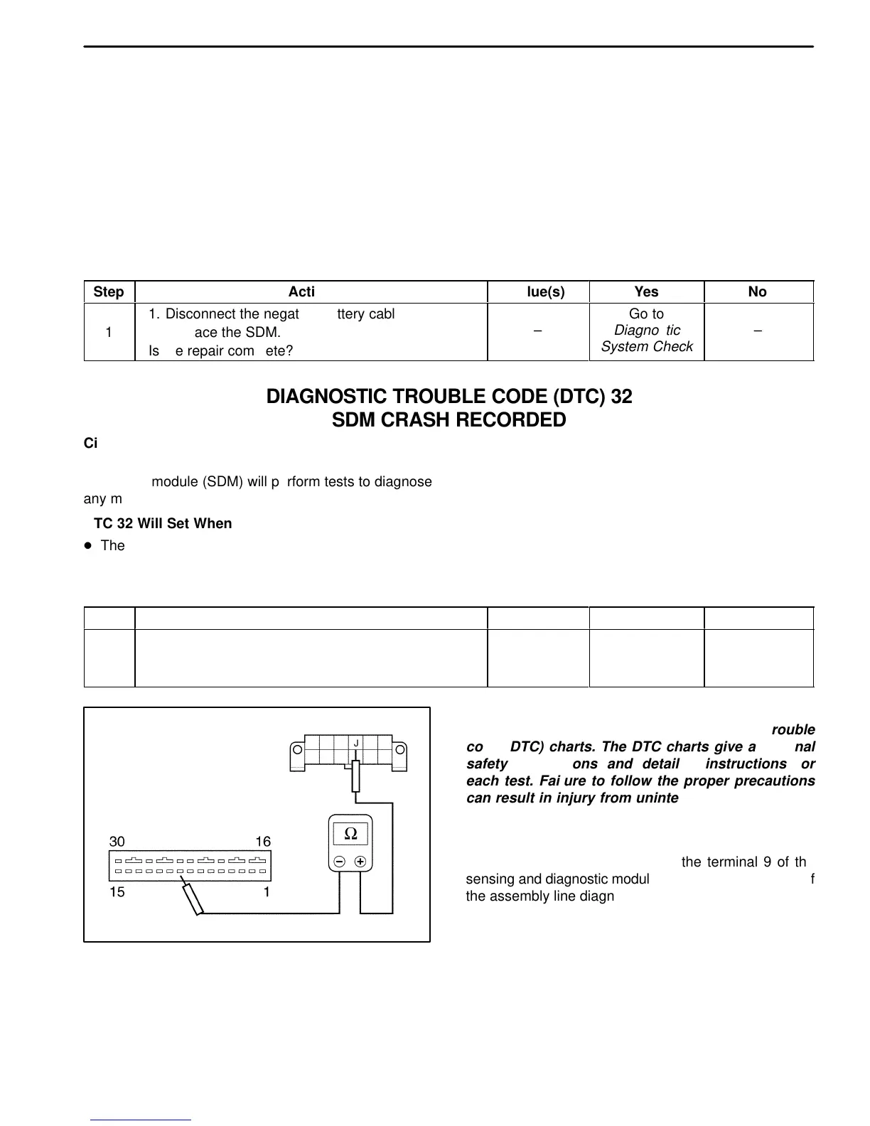
D110B303
Caution: Do not use these illustrations to trouble-
shoot without consulting the diagnostic trouble
code (DTC) charts. The DTC charts give additional
safety precautions and detailed instructions for
each test. Failure to follow the proper precautions
can result in injury from unintended airbag deploy-
ment.
DIAGNOSTIC ILLUSTRATION 1
Checking the continuity between the terminal 9 of the
sensing and diagnostic module and the terminal J (13) of
the assembly line diagnostic link.