9E–14 INSTRUMENTATION/DRIVER INFORMATION
DAEWOO M-150 BL2
7. Install the instrument cluster assembly. Refer to “In-
strument Cluster” in this section.
8. Install the floor console with the screws.
9. Install the passenger’s airbag module to the instru-
ment panel. Refer to Section 8B, Supplemental In-
flatable Restraints (SIR) (For vehicle equipped with
the airbag).
10. Install the glove box assembly to the instrument
panel. Refer to “Glove Box” in this section.
11. Install the hood latch release lever to the instrument
panel. Refer to Section 9R, Body Front End.
12. Install the instrument cluster trim panel to the instru-
ment cluster trim panel with the screws.
13. Install the A–pillar trim panels. Refer to Section 9G,
Interior Trim.
14. Install the signal lamp switch and the wiper switch.
Refer to Section 6E, Steering Wheel and Column.
15. Install the steering column trim cover. Refer to Sec-
tion 6E, Steering Wheel and Column.
16. Install the steering wheel to the steering column.
17. Install the driver’s airbag module to the steering
wheel. Refer to Section 8B, Supplemental Inflatable
Restraints (SIR) (For vehicle equipped with the air-
bag).
18. Connect the negative battery cable.
D109B522
TIE–BAR
(Left–Hand Drive Shown, Right–Hand
Drive Similar)
Removal Procedure
1. Disconnect the negative battery cable.
2. Remove the instrument panel assembly. Refer to “In-
strument Panel” in this section.
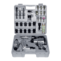
3. Remove the defroster duct hose from the tie–bar.
D Remove the screws (1).
D Remove the defroster duct hose (2).
D19B547A
4. Remove the nuts and the steering column. Refer to
Section 6E, Steering Wheel and Column.
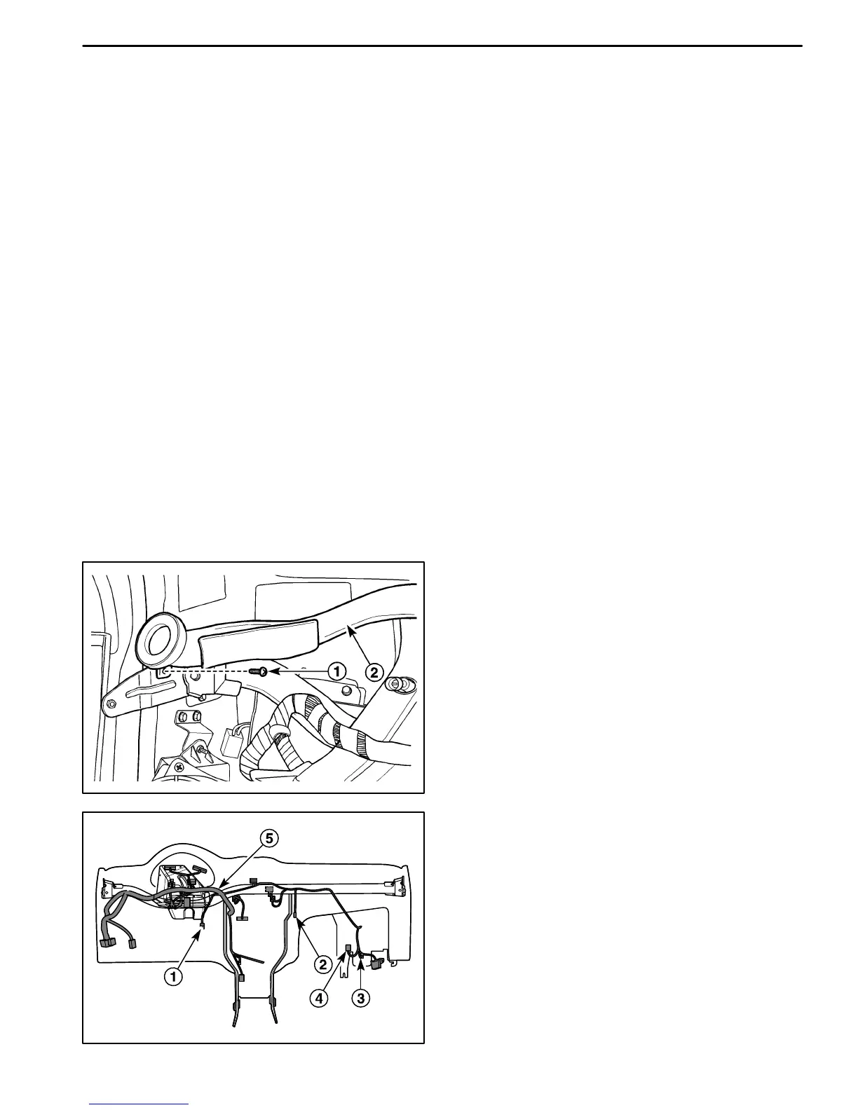
5. Disconnect the electrical connectors and electrical
wiring harness after removing the electrical wiring
harness strips.
D Remove the electrical wiring harness strip.
D Disconnect the brake switch connector (1).
D Disconnect the thermostat connector (2).
D Disconnect the blow motor connector (3).
D Disconnect the blow motor resistance connector
(4).
D Disconnect the electrical wiring harness (5).