Chapter 6
| Switch Management
Understanding the System Status LEDs
– 51 –
Understanding the System Status LEDs
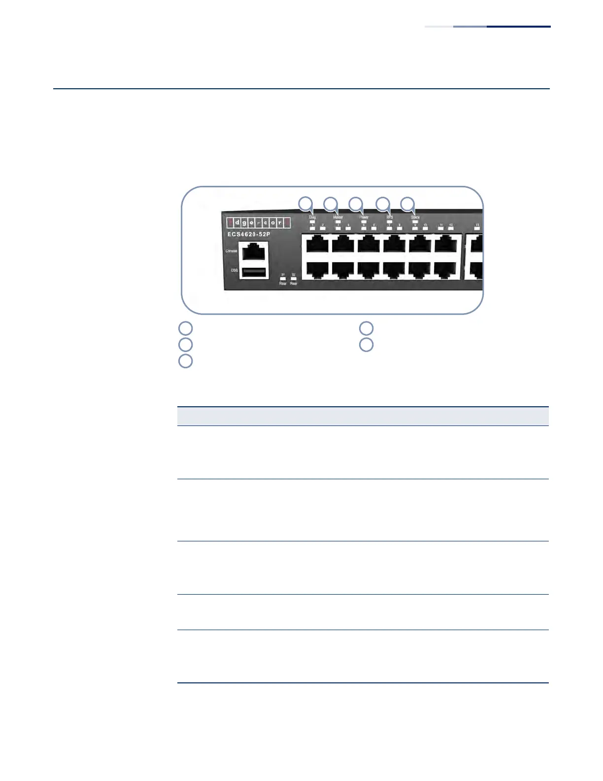
The switch includes a display panel of key system LED indicators. The LEDs, which
are located on the front panel, are shown below and described in the following
table.
Figure 28: System Status LEDs
(
Diag LED RPS LED
Master LED Stack LED
Power LED
Table 11: System Status LEDs
LED Condition Status
Power On Green Internal power operating normally.
On Amber Internal power supply has a fault.
Off Power off.
Diag
(Diagnostic)
On Green The system diagnostic test has completed successfully.
Blinking Green The system diagnostic test is in progress.
On Amber The system diagnostic test has detected a fault or a system
fan has failed.
RPS
(Redundant
Power Supply)
On Green Redundant power supply is receiving power.
On Amber Redundant power supply present, but has a fault.
Off No redundant power supply is present.
Stack On Green The SFP+ ports are operating in stacking mode.
Off The SFP+ ports are in uplink mode or there is no link.
Master On Green The switch is the Master unit in the stack.
On Amber The switch is operating as a Slave unit in the stack.
Off The switch is operating in stand-alone mode.